Rotational dynamics
Rotational dynamics is linked to the propellers because the propellers rotate giving it a force which is called torque. Here are some equations which have some relevance to my project.
Angular motion
Torque Г (N m) = Moment of inertia I (kg m‾²) x angular acceleration rad s‾²
Torque Г (N m) = Force (N) x Distance (m)
Moment of inertia = Mass x (distance from pivot to mass)²
Equations of uniform angular acceleration
ω = ω0 + t
ω²= ω0² + 2 θ
θ = ωt² + ½ t²
ω0 (initial angular velocity) = initial rpm (revolutions per minute) x 2π rad min‾¹
ω (final angular velocity) = final rpm x 2π rad min‾¹
θ (angular displacement) = average angular velocity x Time
With these formulas I can rearrange with certain data to calculate the torque (force) or speed of the propeller.
Motor physics
Calculating Motor Speed:
To Calculate the speed of a induction motor, apply this formula:
Srpm = 120 x F
P
Srpm = synchronous revolutions per minute.
120 = constant
F = supply frequency (in cycles/sec)
P = number of motor winding poles
Hypotheses
What are the properties of a propeller?
What makes propeller more efficient?
Prediction
I predict that the large blade would spin faster because the surface area is
I also predict the revolutions per minute would increase if the speed of the air is increased, and that the difference in rpm would be proportionally to the speed of the air.
Variables
Variables that can affect the experiment
- Speed of air directed at the propeller
- Direction of air
- Other air movement in the room
- Surface area of propeller
- Weight of propeller
- Shape of propeller
- Motor
- Size of fan generating wind
Variables I will change and record will be the speed of the air hitting the propeller and the size of the propeller blades. My measured variable will be the voltage the propeller produces this will determine the speed of the blade.
Apparatus
Different size propellers
Motor
Voltmeter
Fan
Variable supply
Anometer
Clamp stands
Weighing scales
Ruler
Wire
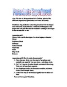
Diagram
Collecting Precise and accurate results
To keep this experiement fair I will make sure the surround air is as still as possible by closing the windows in the lab, I will also measure the distance of the fan to the propeller and make sure both are parallel so the air is travelling directly at the propeller. The measurements I will take will be to 2 decimal places using a digital voltmeter so I can read the measurement more clearly without a error margin from the
Propellers
I had to measure and weight the propellers so I can compare their performance when I run my analysis, I used graph paper and traced the propellers surface area of one blade to estimate the surface area where the air will hit. I weighed the propellers using a digital scale that was precise to 3 decimal places, which I rounded to the nearest half gram. The blade length did not consist of the center hold of the propeller yet the diameter does.
Procedure
Sir would be exerted onto the propeller blade at different settings using the variable supply/fan, I will measure the speed of the air with an anometer this will give me a reading of what the air speed is when it makes contact with the blades, once the fan is turned on the air rotate the propeller this is connected to a motor which will spin and generate electricity (much like wind turbines) I will read the voltage of the electric generated on a digital voltmeter for more precise recordings. The light gate will measure the revolutions per second. To fix the propellers onto the motor I will use blue tac since I do not have the possibility of custom made propellers which can fix onto motors firmly.
Preliminary tests
With my first set up I generated these results
1st preliminary
After analysis these results I noticed many things was not fair and some apparatus did not function well, firstly the results did not make much sense, all the propellers gave individual results which no pattern between them, I realised the fan I was using pushed a area of air less that the largest propeller’s diameter which I assumed would give an advantage to the smaller propellers, so I replaced the fan, the other issue was the 6th propeller I noticed was slightly different shape and a lot lighter so I decided to use only 1,2,3,4,5. The light gate I used was far to slow to record the speed of the propeller and I was advised to use d a strobe laser but I could not aquire one for this experiment. After the changes were made I carried out another preliminary test.
2nd preliminary
This results show a clearer pattern even though the air speed is slower it shows a greater affect on the propellers. I decided I was happy with this layout and decided to keep it like this for my final experiment.
Observations & Results
Test 1
Test 2
Test 3
Observations
After the first test I check propeller number 2 to find out why its performance was much lower than I expected because it is slower than propeller 3,4 and 1 after changing the weight and making sure there was no chips or bends on the blade I proceded with test 2 and 3 and the results were almost the same. Im not sure why this propeller gave these results, I could not find out what was different. I would have to assess it during my analysis.
Analysis
Using the data I recorded from the 3 tests I calculated the average and put them into a new table, using this table I plot a graph and using this as my final results.
Average table
Calculations
Gradients – propeller 1
Started with a gradient of 0.34 but towards the end the gradient changed to 0.036.
Propeller 2
Started with a gradient of 0.26 but towards the end the gradient changed to 0.06.
Propeller 3
Started with a gradient of 0.32 but towards the end the gradient changed to 0.08
Propeller 4
Started with a gradient of 0.3 but towards the end the gradient changed to 0.08.
This shows that it it changes rate of voltage quickly and as the wind speed gets faster the increase of voltage is more gradual this means the as the wind speed increase the speed of the propeller slows in increase, my prediction if there the wind speed increased further it would soon reach a terminal velocity when the propeller will not increase any further
Conclusion
With the data I collected I plotted 6 graphs, 1 on the average of the 3 data sets and then used to compare the 5 propellers, the other 5 were graphs on each indivdual propeller so I can calculate the gradient and compare the shape of the 5.
Each propeller the same shape on the graphs, which showed a pattern of which it would generate more voltage if the air speeded, increased which I predicted, but the change in voltage was not proportional which was in my prediction.
The results from propeller 2 I still cannot explain and do not know why these results are so deferent from the others even though I checked it through again to see if it was the between the sizes 1 and 3.
The gradients I calculated show that it changes rate of voltage compared to the rate of air speed starts off quickly but as the wind speed gets faster the increase of voltage is more gradual, this means the as the wind speed increase the propeller’s speed decreases in the rate of change, my prediction if there the wind speed increased further it would soon reach a terminal velocity when the propeller will not increase any further even if you increased the air speed.
Apart from the anomalous of propeller 2 it clearly shows a pattern that the greater the propeller size the greater the speed, which was as I predicted
Evaluation
My procedure and method
My procedure worked well and was set up easily with no major problems except the light gate which did not matter in the end, all of the apparatus was easily found among the lab apart from the strobe, my method of using a motor as a generator worked well but recording the speed of the propeller as voltage cause few problems as it was not the actually speed of the propeller and just a way to show how much electric it was generating which also meant how fast it was going. Using the motor caused a small problem which didn’t occur to me while I was doing the experiment but didn’t cause much affect as all the propellers span with no trouble, even though the motor cause some friction which made the propeller spin slower than it could spinning on a more free moving pin. Using the fan as a way of spinning the propeller was a good way to test the properties of the propeller because the purpose of a propeller is to create lift or the opposite affect.
Anomalous results
It was clear that propeller 2 gave an anomalous result compared to the other 4, even though it had a bigger surface area than 3 4 it spin slower and the weight was lighter than 1 so theoretically it should have span faster than 3 and slower than 1.
Errors and uncertainties
While recording data when increasing the air speed from one to the other the propeller began to accelerate so I waited till it span at a constant rate, once at this constant rate the rotation was not 100% constant as the air differed slightly caused by dusted or slight movement in the room, this caused the voltmeter to change its display back and forth (at its maximum velocity) thankfully because I took precautions like closing the doors/windows and keeping my movement to a minimum the voltage only differed slightly which made only a slight error range, I used the average of this by judging, this maybe be slightly inaccurate but the error I may have made would only be 0.01 so it was not a major issue.
What I was uncertain about was when I had to change the propellers, this took some force to remove the propellers from the motor which moved the apparatus, but after fixing the next propeller I had to measure the distance between the fan and the motor and make sure the fan and propeller is parallel otherwise it could affect the speed of the propeller, because the layout was not 100% the same each time a propeller was changed I decided to do 3 tests.
The thing that I was most uncertain about the way the propellers were fixed on because the blue tac did not make it 100% secure which could have led to slight sliding of the propeller and motor which would have caused inaccurate result
Modifications
If I had to redo the test in the same space of time I would change the motor, I would look harder to find a more loose motor so I could test slower air speeds so I can produce more accurate graphs, I would also use more sturdy clamp stands and weights to reduce the movement of the apparatus while I change the propellers.
If I had a wider range of resources I would change the motor and propeller so that the propeller would attach itself without much force maybe with a cog shaped out of the center of the propeller so I could fix it onto a motor and assure that there would be no slipping between the propeller and motor while it is spinning, also I would use a strobe light to measure the revolutions per minute more accurately.
Further work
If I had more time and needed to expand my project I would take in mind another important property of a propeller which is the change of angle, and also look into the different shapes and area surfaces, and how they affect the performance of a propeller.