Additional information
The additional information below was found on a web site called and found using the search engine google and the search title ‘simple capacitors’. I have chosen to present this information as it gives a clearer insight into how a capacitor works than I am able to. In addition, it is an independent source of information, which currently backs up my knowledge of capacitors.
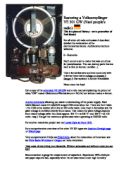
The capacitor is a device that can store energy and is found most electronic circuits. It is made up of a pair of conducting plates separated by a small distance, but not touching each other. When the plates are connected to a charging device such as a battery, electrons are transferred from one plate to the other. This occurs because the positive battery terminal pulls the electrons from the plate connected to it. Consequently, these electrons are pumped through the battery and through the negative terminal to the opposite plate. The capacitor plates then have equal and opposite charges- the positive plate is connected to the positive terminal, and the negative plate is connected to the negative terminal. The charging process is complete when the potential difference between the plates equals the potential difference between the terminals of the battery. The greater the battery voltage, and the larger and closer the plates, the greater the charge that can be stored. In practice, the plates may be thin metallic foils separated in by a thin sheet of paper.
This is an example of what a simple capacitor looks like a re-chargeable battery
Key variables
- Size of capacitor
- Size of resistance
- Size of supply voltage
Chosen variable
I have chosen to vary only the resistance as we have a good range of resistors in school, which will give a large spread of results. Also it would be difficult to alter the supply voltage as a whole class of students are carrying out this experiment at the same time in the same room, all sharing the same supply voltage. This would prove to be impossible to coordinate.
Aims of the experiment
I aim to find out how the size of the resistor will affect the rate at which a capacitor charges. Hopefully, I will find a strong correlation between the formula and my results but also I am hoping for slight differences, which I can explain and improve this experiment to eradicate them from further investigations.
Prediction
As I vary the size of the resistor I expect the rate at which the capacitor charges to vary too. According to scientific theory, the relationship between the size of the resistor and the rate at which the capacitor charges should be that of when I raise the size of the resistor the rate at which the capacitor charges should decrease.
Using the formula (T=RC) I can predict the following: the resistance ( ) multiplied by the capacitance ( ) will equal the time taken for the capacitor to reach two thirds of the supply voltage.
Predicted results using the formula
Preliminary results
This is just a small sample of results to help me plan the main practical. Hopefully it will help me to improve and enable me to plan my experiment more efficiently.
Fair test
To keep this investigation fair I must keep every factor the same except for varying the size of the resistor, which I must keep constant throughout my experiment. To do this, I must always keep the same capacitor as even though there maybe others with the same capacitance they still may vary a little. I must always use the same supply voltage which is 9 volts and the same connection in the class room as the voltage does vary very slightly as you move around the room. The same person must do the timing as reaction times vary and so may the accuracy.
(George Barrett)