Resistance coursework
Hypothesis
I am going to investigate what factors affect the resistance of a wire. There are three main factors which affect the resistance of a wire:
The material of the wire. (What the wire is made out of)
The length of the wire.
The thickness of the wire. (The diameter of the wire)
Resistance is a force which opposes the flow of an electric current around a circuit so that energy is required to push the charged particles around the circuit. The circuit itself can resist the flow of particles if the wires are either very thin or very long.
e.g. The filament across an electric light bulb.
Resistance is measured in ohms. The symbol for an ohm is . A resistor has the resistance of one ohm if a voltage of one volt is required to push a current of one amp through it.
George Ohm discovered that the emf of a circuit is directly proportional to the current flowing through the circuit. This means that if you triple one, you triple the other He also discovered that a circuit sometimes resisted the flow of electricity. He called this resistance. He then came up with a rule for working out the resistance of a circuit:
V/I = R or
V - volts
I - current
R - resistance
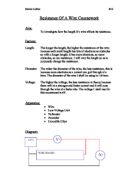
To begin with I am going to investigate which materials put up the highest resistance and I will combine it with the investigation about which length puts up the greatest resistance.
The type of material will make a difference because the electrons have to pass through the material. These electrons find it easier to pass through some materials than others. In this experiment I am going to use copper and nichrome wire. I predict that the nichrome wire will have a higher resistance than the copper wire. I can say this because I know that the electrons have to squeeze together more in order to be able to pass through nichrome wire than they do in order to pass through copper wire. (The more the electrons bump together, the higher the resistance.)
The length of the wire will make a difference. This is because when you have a long wire, the electrons have to squeeze together for longer to be able to pass through the wire than they do in order to be able to pass through a short wire. I predict that the longer the wire, the greater the resistance. If I had a 30 cm wire and a 60 cm wire, the 60 cm wire would have a resistance twice that of the 30 cm wire.
For this experiment I will be using a voltmeter, an ammeter, five wires, two crocodile clips, some nichrome and copper wire and a power pack. The wire will be: 26 swg of copper and 26 swg of nichrome. The diameter of the wire will be kept the same so that it is a fair test. The voltage will also be kept the same, although the readings may not be exactly the same each time. For the lengths I will be using 10, 20 and 40 cm wires, this is because I can then see if my prediction about doubling the length is correct.
To make this test fair I should take more than one result so that I can work out an average, this will help prevent any wayward results.
Method
. Collect apparatus: a voltmeter, an ammeter, 5x wires, 2 crocodile clips, 10, 20 and 40 cm of both nichrome and copper wires and a power pack.
2. Set apparatus up as shown:
3. Set the power pack on as low a voltage as possible. (So that there is not too high a current passing through the circuit.)
4. Place the 10 cm ...
This is a preview of the whole essay
To make this test fair I should take more than one result so that I can work out an average, this will help prevent any wayward results.
Method
. Collect apparatus: a voltmeter, an ammeter, 5x wires, 2 crocodile clips, 10, 20 and 40 cm of both nichrome and copper wires and a power pack.
2. Set apparatus up as shown:
3. Set the power pack on as low a voltage as possible. (So that there is not too high a current passing through the circuit.)
4. Place the 10 cm of nichrome between the two crocodile clips to complete the circuit.
5. Turn on the power pack and record what the ammeter and voltmeter read.
6. Replace the 10 cm of wire with the 20 cm of nichrome remembering to keep the voltage the same. Turn on your power pack and record what the ammeter and voltmeter say.
7. Change the wire to the 40 cm of nichrome wire and repeat the experiment.
8. Do the same for the copper wires.
9. Work out the resistance for all the results using Ohm's law. V = I*R
0. Record your results in a graph.
Results
Conclusion
My hypothesis was correct. The nichrome wire has a higher resistance than the copper wire and the longer the wire, the higher the resistance.
Ohm's law states that the current flowing through the circuit is directly proportional to the voltage applied. (If you double one, you double the other.)
I worked out the resistance of the wires by using the formula:
V/I = R or
This happens because of the electrons that flow through the wire. These electrons travel at a steady pace, when they come to a different piece of wire, they have to slow down in order to be able to pass. (This is why the current differs). While moving through the wire, the electrons need to squeeze together. This is because there is not enough room/space for them to pass evenly through. The more the electrons have to bump together then the higher the resistance. This is because it will take longer for them to pass from one side of the wire to the other side. This is because the current is slowed down. (The longer the wire, the longer the electrons have to stay squashed together, and so the longer they take to pass through the wire and the higher the resistance. The material of the wire makes a difference because it is harder for electrons to pass through some materials than it is for them to pass through others. (Some wires cause the electrons to bump together more than others.)
I put my results into graphs although they are not on the same axes because the resistance for copper wire is so low. I had to draw a line of best fit on all the graphs because there were a few wayward results.
* The graphs which compare the length of the wire to the resistance it gives travels in a straight line through the origin. This means that the size of the length is directly proportional to the resistance it gives. I can work out the gradient of this line by dividing the height of the line by the width. (Gradient = height/width)
The gradient of the graph for copper wire is: 0.01/9 = 0.001
The gradient of the graph for nichrome wire is: 1/16 = 0.0625
As the gradient of the second graph is higher. I can say that the resistance for the nichrome wire increases more rapidly as the length of the wire increases than the resistance for the copper wire. The results for the copper wire have a pattern to them. The result for 10 cm is 0.011, and the result for 20 cm is 0.022, so I can predict that the result for 50 cm will go 0.055 and so on.
* The other graphs which compare the current of the wire to the length of the wire also travel in a straight line. These graphs however travel downwards, this means that they will have a negative gradient. As the current decreases, the length of the wire increases.
The gradient of the copper graph is: 30/-12 = -2.5
The gradient of the nichrome wire graph is: 0.2/-8 = -0.025
As the gradient of the second graph is lower I can say that as the length increases the flow of current decreases faster in copper wire than in nichrome wire.
There were a few wayward results. This could have been because the wires were not exactly the correct length or because I did not read the voltmeter and ammeter accurately. The wires might have been over-heated The temperature of the wire will affect the resistance. Hotter wires will have a higher resistance than cold wires. To improve my results I should have obtained more than one result for each wire and length. I could have then worked out an average for more accurate results.
The method I used was fine, although it was extremely hard to collect any results for copper wire. This is because copper has such low resistance. It has a low resistance there will be a large current. The ammeters we have in school cannot read such a high current. Without the current I cannot work out the resistance of the wire. I ended up using some results I had already collected the last time I did this experiment.
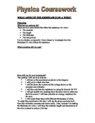
Hypothesis: Does the Diameter of the wire affect the Resistance?
Ohms law states that if the cross section of the wire is uniform thenthe resistance is proportional to the length and inversely proportional to the area of the cross section. The diameter of the wire will have an affect on the resistance of a wire. This is because the electrons have to squeeze together more to pass through a thin wire than they do to pass through a thick wire.
I can predict that the thinner the wire the higher the resistance. If I had a piece of wire 1 mm in diameter and a piece of wire 2 mm in diameter, how much would the resistance increase by? Would the resistance double because the diameter has doubled? Would it increase four times because the cross section has increased by four? Or does it do something else?
r2 is how to calculate the area of the cross section.
0.52 = 0.25, 0.25* = 0.79cm2 (Area of cross section of a 1mm wire)
2 = 1, 1* = 3.14cm2 (Area of cross section of a 2mm wire)
I will need 5 x wires, an ammeter, a voltmeter, 30cm of 32swg nichrome wire, 30cm of 26swg nichrome wire, 30cm of 22swg nichrome wire, 2 crocodile clips, and a power pack.
The diameters of the wires are:
32swg = 0.28mm
26swg = 0.45mm
22swg = 0.71mm
The area of the cross section of each of these are:
0.142 = 0.0196* = 0.06cm2 (32swg)
0.2252 = 0.05* = 0.16cm2 (26swg)
0.3552 = 0.126* = 0.39cm2 (22swg)
To make this test fair I will keep the length of the wire the same and I will also keep the voltage the same. I will do the same as I did before except this time I will be using different wires.
The Plan
. Collect apparatus: A voltmeter, an ammeter, 5 x wires, 2 crocodile clips, 30cm 32swg nichrome wire, 30 cm 26swg nichrome wire, 30 cm 22swg nichrome wire and a power pack.
2. Set the apparatus up as shown.
3.
4. Set the power pack on as a low a setting as possible. (So that the volts aren't too high for the voltmeter to read.)
5. Place the 32swg nichrome wire between the two crocodile clips to complete the circuit.
6. Replace the 32swg nichrome wire with the 26swg nichrome wire. Remember to keep the voltage the same, or as near as you can get it.
7. Record what both the ammeter and voltmeter say.
8. Change the wire to the 22swg nichrome wire and repeat the experiment.
9. Work out the resistance for all your results by using Ohms law.
V=I*R or R=V/I
0. Record the results in a graph.
Results
Nichrome Wire
Diameter/mm
Voltage/volts
Current/amps
Resistance/ohms
0.28
0.6
0.14
4.29
0.45
0.6
0.45
.33
0.71
0.6
0.74
0.81
Conclusion
My hypothesis was correct. The thinner the wire, the higher the resistance and the thicker the wire, the lower the resistance. This is because there are electrons in a circuit. These electrons travel around the circuit at an even pace. When they come to the wire I placed in the circuit the electrons have to slow down in order to be able to pass through it. This causes a resistance. The electrons will bump together, and the more they bump the higher the resistance of the wire. In a thin wire these electrons have to squeeze tightly together in order to pass through, however in a thick wire these electrons do not have to squeeze together as much to be able to pass through. So the more they squeeze together, the higher the resistance.
After collecting my results I drew three graphs. The graph which compares the diameter of the wire to the resistance of the wire travels in a curve. The graph shows that the resistance in Ohms is inversely proportional to the diameter of the wire. (This means that if you double the diameter you halve the resistance). The graph which compares the area of the cross section and the resistance of the wire also travels in a curve.
This proves Ohm's Law as he states that if the area of the cross section of the wire is uniform then the resistance of the wire is inversely proportional to the cross section. The third graph which compares the diameter of the wire to the current flowing through the wire travels a straight line through the origin. This means that the diameter of the wire is directly proportional to the current flowing round the circuit. If you double the diameter, the current also doubles because there is less resistance as the diameter increases.
The gradient of this graph is (Height divided by width) 1.5/0.12 = 12.5.
My working method was a good one although there were a few wayward results. This could have been avoided if I had had the time to repeat the experiment and work out an average. They could have been slightly out because I did not measure the length of wire correctly or because I did not read the ammeter and voltmeter accurately. For this investigation I used 32swg, 26swg and 22swg nichrome wire because they were the only ones that I had. (It might have been better if I'd used more thicknesses, because then the graphs would have been smoother).
Summary of Ohm's law
The current flowing through the circuit is directly proportional to the voltage applied to the circuit. (If you double one, you double the other.)
The cross sectional area is inversely proportional to the resistance of the wire. (If you double the cross sectional area, you halve the resistance.)
Ohms's law states that:
V = I*R and
= RC/L
V = voltage applied, I = current
R = resistance of the circuit, C = cross sectional area
L = length of the wire, and = resistivity of the wire.
Sanjay Naker 11LC Science `
Mr Reade