Prediction
I think that as the size of the wire increases the resistance of the wire will decrease. I believe this as every atom has about one free electron and the greater the size of the wire, the more atoms the wire has. The free electron is important as it moves from a place where there are too many electrons to a place lacking electrons. As a thicker wire has more spaces it is easier for the electrons to move, but in a thinner wire there is less space it is harder for the electrons to move we call this resistance.
CROSS SECTION OF AN ATOM
CROSS SECTION OF A THICK WIRE
CROSS SECTION OF A THIN WIRE
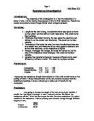
Pre Test
I decided to do a pre-test because I thought that it would aid me in completing the investigation in the way that would give me the best results. In my pre test I decided to see:
- Which voltage is the best to use 1v, 3v or 5v.
- Which length of wire to use.
- Which lengths of the wire to measure.
- Which apparatus to use.
I feel that the pre test, which I did, was a valuable use of my time. It enabled me to test different methods of doing the investigation, which would enable me to produce clear and concise results.
The first step was to make sure the circuit worked and connections were in place. I experimented to see what would be appropriate length of wire to choose; I found that a piece of wire100cm long as it enabled me to take 3 measurements of the thickness of the wire. I decided to measure the thickness of the wire using a micrometer at 3 points 25cm, 50cm and 75cm this would enable me to take an average thickness and therefore obtain fairer results. I decided to power the circuit at 3 volts as it gave us the clearest results and would not heat up the wire too much. I also timed how long it took to take a reading so I could work out how many times I could repeat the experiment.
Apparatus
The apparatus that I decided to use was:
-
Power Pack – To power the circuit, which we will use.
-
Wires – To connect the circuit
-
100cm ruler – To measure the length of the wire.
-
Crocodile clips – To connect the wires to the rest of the circuit.
-
Voltmeter – To measure the potential difference (volts).
-
Ammeter – To measure the current (amps).
-
Copper wires – The wires will be the same length but different ngnfjfhjkgkgkghugiiiwidths
-
Micrometer – A micrometer is a measuring device, which cans hkjgkhjlkhjkhjkhjkhienable the user to measure to 100th of an iiiiiiiiiiiiiiiiiiiiiiiiiimpmillimetre.
Method
Step-by-Step Method
- Set up the apparatus as shown on the previous page.
- Measure the widths of the five wires using a micrometer at 250mm, 500mm and 750mm and then take the average width.
- Turn on the power pack.
- Ensure that the voltage is 3v.
- Record the current from the ammeter.
- Repeat steps 3 to 5.
Fair Test
To help me make my test fair I had already made the circuit up to check that the circuit works and that the resistance changes when different wires with different widths were used. I will take more than one set of values making sure that the set-up is the same each time. I need to make sure that I only change the wires and that the other variables remain constant such as the temperature of the wire and the material it is made of and the length of the wire.
Results
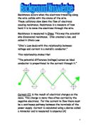
To work out the resistance of the wire I divided the potential difference by the current and plotted the average resistance against the average diameter of the wire on the graph.
To work out the surface area of the wire I used the formula;
The graphs shows that the line of best fit descends fairly steeply at first but then it starts to even out when the diameter of the wire becomes less than 0.4mm. I feel that this is because; the atoms are the same size in all of the wires but in the wider wires there are more gaps, which enables the electrons to pass through with some ease. When the wires have a diameter that is lower than 0.4mm there is considerably fewer gaps making it much harder for the electrons to pass through thus creating more resistance. This is basically my prediction.
Evaluation
In the experiment I received some anomalous results, however in most cases the results were not far out since the points are either on the line of best fit or are close to it. The only obvious anomaly was in the graph “The average diameter of a wire against its resistance” but this could be an error either in the obtaining of the data or the recording of the data and therefore I will not account it.
To reduce anomalous results, I would try to keep the temperature of the wires equal, since as the temperature increases the resistance of the wire increases. I could do this by recording the results 1 minute after the wire has been connected to the circuit. Also measuring the length of the wire more accurately perhaps with the use of callipers would improve the accuracy of my readings.
Another limitation was that we could not measure the wire accurately, as it was not straight though we tried to make it as straight as possible and our rulers, were not accurate enough.
I feel that the use of a micrometer greatly aided the investigation it helped us to obtain extremely accurate results.
To further this investigation I would change the type of metal used and see if I could draw the same pattern of the resistance being proportional to the potential difference with a variety of metal wires.
Given the research, and the limited results of my experiment, it appears that a firm conclusion can be draw, that resistance is proportional to the size of the diameter of a wire.