What is Resistance?
The Metallic Structure of a Conductor
The atoms which make up a metal are arranged into four different layers. Metals which are in a regular structure are packed closely. There are spaces between the atoms, when they are arranged in layers because the atoms are spherical in shape.
The second layer can fit into the gaps created by the previous layer because it is offset. Each following layer can fit into the gaps created by the previous layer for the reason that it is offset as well. You can compare the structure to the way oranges are stacked up on a fruit stall.
In the total volume, atoms of the first two types take up78% of the space, whereas the other types take up 68% of the entire volume.
Metal atoms will always try to occupy the greatest amount of volume. For instance, they have the smallest amount of gaps. The type of metallic structure a metal gets relies of the radius of the atom and the charge it generates when it loses its valence electrons.
The valence electrons of a metal atom are fairly easily removed, with the construction of metal cations.
Then the valence electrons from every atom consequently come under the influence of a huge amount of cations.
The valence electrons are free to travel through the structure and are no longer situated in the outer shell of any one atom and are consequently called delocalised electrons, frequently identified as the ‘sea of electrons’
The elimination of the electrons leaves layers of cations behind. The cations electrostatically repel away from each other, however they are held in position by the attraction of the cations to the delocalised electrons clouds between them.
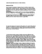
How the Charge is conducted
A chemical reaction (called electrolysis) takes place in the inside of a cell or battery of cells, which causes electrons to be pushed or forced away from the cell.
Therefore the connecting wire attached to the negative terminal becomes negatively charged. The electrons in the connecting wire are repelled away from the build up of charge.
The next segment of the wire in turn will become negatively charged and this procedure will carry on around the circuit.
The electrons are able to perform like this for the reason that they are locomotive due to their delocalised nature.
There is no time limit as one set of electrons repels another; this movement of electrons take place similarly.
Correspondingly as electrons are pushed out of the cell, the electrons are pulled back in to replace them. The circuit remains detached overall even though there is a movement of electrons.
The Obstacle Course Model of Resistance
The flow of charge (electrons) through a conductor can be compared to an obstacle course. This correlation is sometimes called the Obstacle Course Model of Resistance.
As the electrons shift from one part of the conductor to the other, they have to find their way round past the layers of cations (making up the metallic structure of the conductor), which work as obstacles to the solid flow of electrons.
Any Factor that causes there to be additional obstacles or makes it more complicated for the electrons to flow will develop the resistance of the conductor by decreasing the rate of flow of charge.
Resistance
The resistance of a conductor is its opponent to the flow of electrons through it.
As electrons move down a wire, the atoms of the wire can decelerate or defy the flow of electrons.
A good conductor has low resistance and a poor conductor has a high resistance. Resistance is measured in Ohms, Ω.
Electrons travel better through certain conductors than others when a potential difference is utilised. The greater the resistance the more potential difference is needed to push the current through the conductor.
The Factors affecting Resistance
There are four factors that affect resistance:
- The length of the conductor, L
- The cross sectional area of a conductor, A
- The resistivity (type or nature) of the conductor, ρ
- The temperature of the conductor
The Length of the Conductor
The length of a conductor is similar to the length of a hallway. A shorter hallway would allow people to move through at a higher rate than a longer one. Resistance in wire depends on how thick and how long it is, and what it's made of. The thickness of wire is called its gauge. The smaller the gauge, the longer the wire.
The Cross sectional area of a Conductor
The cross-sectional area of a conductor (thickness) is similar to the cross section of a hallway. If the hall is very wide, it will allow a high current through it, while a narrow hall would be difficult to get through due to it's restriction to a high rate of flow. This results in a larger current which leads us to say that the resistance is less in a wire with a larger cross sectional area.
The resistivity (type or nature) of the Conductor
Different types of metal are used in making wire. You can have copper wire, aluminium wire, even steel wire. Each of these metals has a different resistance; how well the metal conducts electricity. The lower the resistance of a wire, the better it conducts electricity. Copper is used in many wires because it has a lower resistance than many other metals.
The Temperature of the Conductor
A piece of metal can be made to act like a heater. When an electrical current occurs, the resistance causes friction and the friction causes heat. The higher the resistance, the hotter it can get. So, a coiled wire high in resistance, like the wire in a hair dryer, can be very hot.
How Current and Voltage are related-Ohm’s Law.
Ohm’s Law states for a conductor at a constant temperature, the current will increase and the voltage will decrease, as long as the resistance stays the same. Current is described as being proportional to voltage. The variable resistor is used to alter the current flowing through the circuit. The ammeter and voltmeter values are recorded ate different positions of the variable resistor. If the ammeter and voltmeter readings are plotted on a gradient, a straight line is produced. The gradient of the graph will give the resistance. The steeper the gradient the higher the resistance.
How variable resistors work
When you move the slider to position 2, the light will go dimmer because it has to go through more coiled wire, whereas if you move the slider to position 3, the light will go brighter because it has less coiled wire to go through.
This variable resistor has 3 connect points, but you don’t use one of them. You can move the slider to brighten the light bulb.
What is current?
Current is a group of electrons that move very fast in different directions. They move very fast around a circuit.
Equation for current is: I = Q/t
Current = Change/time
The shorter the time the higher the current will be.
What is Voltage?
When the battery is put into the circuit, chemical energy occurs in the cells and the cells are often referred. The cell pumps electrons around the circuit. This reaches the bulb, which then produces light and heat energy.
Voltage (potential difference, p.d) is a measure of how much electrical energy can be transferred per unit of charge. When thinking about charge a larger number of electrons are considered. This larger number of charge is called the coulomb. The reason is the charge of the electron is extremely small.
V = w/Q
V = voltage, w = work (joules, change in energy), Q = charge
Voltage or potential difference is a measure of the difference of electrical potential energy of electrons between two points.
W = V*Q
C = 6*1018
Each electron has 5J and when they go down the circuit after being pushed out of the cell. When they reach the beginning of the first voltmeter, they still have 3J left. However, when the electrons reach the middle of the two voltmeters they only have 1.5J left because the first lamp has used the other half of the energy. When the electrons reach the end of the second voltmeter they do not have a single joule left because the energy has been used by both of the lamps. The electrons carry on without any joules until they reach the battery and then they regain their 3J and the circuit carries on.
What is Resistance?
The electrical resistance of a circuit component or device is defined as the ratio of the applied to the which flows through it. If the resistance is constant over a considerable range of voltage, then , I = V/R, can be used to predict the behaviour of the material.
Book & Internet References Theory and diagrams taken from the following books and internet sites
- http://www.bearwoodphysics.com/6physicsimages/5schwork1.8.gif
Prediction
What will happen? As the length increases, the resistance will increase.
Why will this happen? Because the electrons will have more cations, the electrons will find it harder to go from one side to the other side.
Fair Testing
Definition
‘Fairness’ implies that the outcome of the activity truly depends on what is being investigated, and is not being distorted by other external factors. Therefore a fair test is one where all the variables are kept constant or the same, except the variable that is being investigated. A variable is anything that can change and which may influence the outcome of the investigation.
List of variables
- Length of a wire.
- Temperature of a wire.
- Resistivity of a wire.
- Thickness of a wire.
- Person that measures the length.
- Person observing the metre readings.
- Number of variables.
- Position of the variable resistor needs to stay constant.
- Number of times you do the experiment to get the average.
- Apparatus needs to stay the same, so you need to do it on the same day.
Statement of fairness
To make it a fair test, I am going to keep all the variables the same, except the length which I am going to change. I am going to take the measurements of the voltage and the ammeter readings.
Range of Measurements to be taken (for the variable being tested)
I will take the ammeter and voltmeter readings of different lengths. The different lengths will be in 10cm increments, from 0cm to 100cm.
Experimental Procedure
Apparatus:
- 2 Batteries
- Voltmeter
- Ammeter
- Metre ruler
- Variable resistor
- Rheostat
- 1m wires mounted on a metre ruler
- Crocodile clips
- Connecting Wires
Diagram:
Method:
When I set up the apparatus as the diagram above, I will put the slider in the middle of the variable resistor and I won’t change its position throughout the experiment. I will get a metre ruler, which has wires mounted on it. I will get the crocodile clips and put one of the clips on 0cm and the other clip on 10cm. I will read the voltmeter reading as well as the ammeter reading. I will then take the other crocodile clip from 10cm and put the clip on 20cm. I again will read the voltmeter and ammeter readings. I will do the same for 30cm, 40cm….100cm. I will repeat the experiment 3 times so the experiment will be a fair test.
Safety Precautions
I have thought about the safety precautions and I don’t think there are any precautions to take. The wire could get hot if the voltage was too high, but in this particular experiment the voltage is supposed to be low.
Results
Results Table
Results (trends or patterns of observations)
From my table you can see that as the length of the conductor increases the resistance and voltage also increase but, the current decreases. Each time the length of the conductor doubles the resistance more or less doubles as well. The average is only really useful when the voltage and current are about the same. If the numbers are not around the same figure the average wouldn’t really mean anything. It wouldn’t be a true reflection on the other results.
Conclusion
In the planning part of this investigation I predicted that as the length of the conductor increases the resistance will also increase because the electrons will have more cations, the electrons will find it harder to go from one side to the other side.
From my results table you can see that as the length increases the resistance will also increase. When the length goes from 40cm to 80cm, the resistance goes from 3.96to 7.95
The reason it happens is that in my theory I stated that the length of a conductor is similar to the length of a hallway. A shorter hallway would allow people to move through at a higher rate than a longer one. Resistance in wire depends on how thick and how long it is, and what it is made of. The thickness of the wire is called its gauge. The smaller the gauge, the longer the wire.
Calculation of the percentage errors from the graph
Evaluation
How accurate was the investigation?
I think the investigation was quite accurate because I repeated the experiment 3 times and the results in the results table were all close to each other. The replicates are close to together, which means I could calculate a representative average. The apparatus was accurate because I had the right amount of everything I needed. However, if the connecting wires were a bit thinner than it would have been an even more accurate investigation. Overall I think the accuracy of the apparatus was good enough for this particular experiment because it is standard and the majority of the schools in England also use this apparatus. I don’t think that the method could have lead to any inaccuracies, because everything was more or less accurate. The line of best fit looks perfect and there aren’t any anomalous results.
Was this a suitable procedure?
It was a suitable investigation because I got what I expected and it proved my prediction. Also, a lot of people done this investigation like this because it is good. My graph is also good, so I know the suitability of the investigation is positive.
Was the evidence sufficient to support a firm conclusion?
Yes, because if you look at my graph, it was done to a good degree of accuracy. As the length doubled, the resistance also doubled, so it was reliable. Also the % of error was less than 5.00% all the time. The replicates are close to the average. I got what I wanted because I did some research so I knew what to expect.
How could the investigation be improved?
Improvements
I would do the experiment more time to get a better average. I would do the investigation 3 times which would mean I could do it on 3 separate graphs with the same apparatus. I would also use a longer wire from 1m to 2m.
Further work
After doing this investigation, I could investigate another variable such as resistivity (type of wire).
I would do the experiment by doing the following;
- I would set up the apparatus.
- I would cut 30cm of copper, tungsten, constantan, nichrome and steel wire.
- I would measure the voltmeter and ammeter readings.
- I would calculate the resistance.
- I would repeat the experiment 3 times to get an average voltage and an average current.