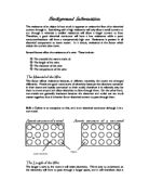
“The thinner the wire the less channels of electrons in the wire for the current to flow, so the energy is not spread out as much.”
Therefore the higher the resistance will be.
Variables
- Length of wire
- Thickness of wire
- Material the wire is made from
- Temperature of the wire
- Temperature of the surroundings
Hypothesis
I predict that the length of the wire will affect the resistance of the current; I have read in “resistance by David anges” this is because as you increase the length of wire the resistance will increase there will be some heat given off the wire, this will also affect the readings because the heat given off isn’t consistent.
I am going to use a digital multimeter to measure the resistance instead of a voltmeter or an ammeter because a digital multimeter gives a specific and precise reading and because n error can occur when either taking the results or calculating the resistance.
I am going to take 10 intervals at 10cm, this is so I can have a verity of readings and a range to work from and each time I take the results I will
Make sure the wire is at room temperature.
I predict that my graph will look like this
Fair testing
To make sure my experiment a fair test I am only going to change the length o the wire.
I am going to keep the invariable the circuit components; battery, connecting clips, multimeter, resistor (wooden stick that has a wire attached to it), and the setting on the multimeter which is 200 ohms (Ω) the same.
Apparatus
- A wire with a crocodile clip at the end
- A multimeter
- A wooden stick with 100cm wire
Method
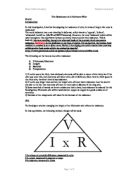
- Get the multimeter, the wires, the battery and the wooden stick. Join all the apparatus together using the connecting wires making sure the longest one with a crocodile clip is a 0mm.
- The crocodile clip is moved up the wire, stopping at 100, 200, 300, 400, 500, 600, 700, 800, 900 and 1000mm each time recording the multimeter reading.
- When you have done this process repeat the experiment.
Diagram of experiment
Safety
- make sure that all electrical equipment is not wet and keep water away from electricity
- all laboratory rules apply
Preliminary experiment
The reason for doing a preliminary experiment is to get an indication of the patterns that would occur in the results. Also, it was a practice so if I made any mistakes then, they could be fixed so that for the real experiment, the minimum mistakes would be made. These preliminary results are very useful as from them, I can check to see if my prediction was correct. From my actual experiment I will record the fist reading at 0mm.
Results
Final experiment
Theses were my results for my final experiment;
-
00mm = 00.4Ω
-
1000mm = 06.5Ω
- The width of the wire was constant at 1mm ( I used a micrometer to be precise with the width)
Graph
Analysis
My graph shows that the increase of the resistance is due to the increase of the wire, the resistance is greater.
The graph above is of a straight line through the origin. This means that resistance is directly proportionate to length; this signifies that it is predictable and significant because if the length is 200mm, the resistance is 1.3Ω; therefore if the length is doubled 400mm then the resistance is also doubled 2.6Ω.
This is because of the scientific idea, shown in the planning that if you double the length of the wire, you double the number of atoms in the metal, and so doubling the ‘jumps’ causing a greater resistance: the results support my prediction well because the results turned out the way I had expected. The graph supports what I thought the graph would look like, but the only difference is that my results went exactly the same only one was different (05.2, 3Ω) and that my graph doesn’t go through the origin. This maybe because there will always be some resistance in the apparatus, during the experiment.
Evaluation
The experiment was fairly reliable as most of my readings were the same but one wasn’t, this may have been because the wire connecting to the multimeter may have been because the wire connecting the multimeter may have caused a resistance, I have seen this when measuring the resistance at 00mm I had a resistance of 00.4Ω. This has made the experiment less accurate thus the wire connecting the multimeter giving of this reading was not correct. Using scientific knowledge we know that if there is a length of wire, then there will be resistance therefore if there is no wire, then there is no resistance, and at 00mm there should be no resistance. I believe this was the cause of the 0.4Ω reading.
Measuring the lengths of the wire is also an inaccuracy as the rulers we used are not exact, and it’s difficult to get an accurate reading of the length using the eye. As the wire might not be completely straight, it may have different thicknesses throughout the wire.
And we know the thinner the wire the more resistance; (but after measuring the wire the thickness of the wire was constant at 1mm)
As you can see in the thick wire the electrons can move without any resistance where as in the thinner wire there is hardly space for the electrons to move causing resistance.
These would have would have been difficult to improve on as they were reasonably accurate, and there were no anomalous results. Each of my readings was the same and most of them when you double the length you would double the resistance most of the time. But if I were to do this experiment again, I would use a different micrometer (to see if there were different in widths) or I would have used an unused wire, I would also try to provide a way if possible of a wire connecting to the multimeter but not causing any resistance what so ever, also as temperature might have affected the resistance I would measure the temperature every 2 readings to see if there is a increase in temperature (then that would be part of the resistance).
The experiment was reliable in a sense that I had no obvious anomalous results yet I had a small one; at 800mm there was 05.3 and 05.2 resistance when repeated at an 800mm interval and had a reading of 05.3mm. This may have been because the temperature may have risen and added extra resistance or the apparatus may have added resistance.
Bibliography
Potential difference – modular science for AQA by Keith Hirt, Mike Hicock, Daivid sang, Martin Stirrup
Ohms law-
prediction –
http//www.psicforyou.com/resistance25163.shtml
Resistance by David Anges