Below are a few paragraphs from a website about circuits.
“In a parallel circuit, electrical devices, such as incandescent lamps or the cells of a battery, are arranged to allow all positive (+) poles, electrodes, and terminals to be joined to one conductor, and all negative (-) ones to another conductor, so that each unit is, in effect, on a parallel branch. The value of two equal resistances in parallel is equal to half the value of the component resistances, and in every case the value of resistances in parallel is less than the value of the smallest of the individual resistances involved. In AC circuits, or circuits with varying currents, circuit components other than resistance must be considered.
If a circuit has a number of interconnected branches, two other laws are applied in order to find the current flowing in the various branches. These laws, discovered by the German physicist Gustav Robert Kirchhoff, are known as Kirchhhoff’s laws of networks. The first of Kirchhoff's laws states that at any junction in a circuit through which a steady current is flowing, the sum of the currents flowing to the point is equal to the sum of the currents flowing away from that point. The second law states that, starting at any point in a network and following any closed path back to the starting point, the net sum of the electromotive forces encountered will be equal to the net sum of the products of the resistances encountered and the currents flowing through them. This second law is simply an extension of Ohm's law.
The application of Ohm's law to circuits in which there is an alternating current is complicated by the fact that capacity and inductance are always present. Inductance makes the peak value of an alternating current lag behind the peak value of voltage; capacitance makes the peak value of voltage lag behind the peak value of the current. Capacitance and inductance inhibit the flow of alternating current and must be taken into account in calculating current flow. The current in AC circuits can be determined graphically by means of vectors or by means of the algebraic equation.”
Reading that I will take
I will take three sets of readings from my experiment. These will be Test 1, 2 and 3. I will have to use a suitable table record my results. The reading will be taken from a voltmeter and ammeter. These are digital multi-meters that produce accurate results.
This is the table I will be using:
Safety Issues
The experiment has to be safe. Due to having 4 working in a group, the safety issues will have to be obeyed.
- The power pack has to be switched off when not in use, just in case some one gets injured from electrical current.
- Bad use of equipment. People can get hurt if some one decides to swing wires with anything attached to them.
Will the test be fair?
To keep my experiment fair, I need to keep the thickness same when investigating length. Since the temperature of the wire may affect the resistance of the wire, I shall keep the current through the wire low so that wire will not heat up. I shall use 10, 20, 30, 40, 50, 60, 70, 80, 90, 100cm length of each wire in turn. I shall take the readings from the voltmeter and ammeter to find out the resistance for each length of wire. I will choose the thickness of the wire. My test will be a fair test because:
- I will use the same power pack voltage throughout the experiment.
- I will measure the length of the wire correctly.
- The same piece of wire will be used throughout the experiment.
- The same resistor will be used throughout the experiment.
- The ammeter and voltmeter used must contain the same scale throughout the experiment otherwise we will end up with uneven results.
My Prediction of what the experiment will be like
My prediction is that when the length of the wire is increased the resistance will also increase. Because as the length of the wire is increased the current will find it hard to flow through the wire. I think that if I increase the length of the wire, the current in the wire will increase and therefore increasing the resistance. This is because the free electrons will have longer to travel and there are going to be more collisions with atoms in the wire. If I decrease the length of wire, the current through the wire will decrease and again this will therefore decrease the resistance because the free electrons have less to travel and there are fewer collisions with atoms in the wire.
Ohm’s Law
The Apparatus
- These are the equipment I will be using in my experiment in detail.
- The power pack will be a safe power device used in the experiment. It will be set from 2-8 volts maximum.
- Ammeter (Digital): This will be used to measure the current flowing through the wire.
- Voltmeter (Digital): This will measure the voltage in the wire.
- Meter of Nichrome wire: This is the wire we will be using for the experiment. It will not be changed otherwise the experiment will not be a fair test.
- Variable Resistor: The variable resistor will be used to increase and decrease the resistance through the wire.
Resistors can be used in light bulbs and all home electrical appliances. Filaments in bulbs are made from tungsten wire. When a current floes through tungsten wire it becomes very hot and glows white. The temperature goes up drastically to about 2500+ Celsius. The wire melts at about 4000 degrees. In electrical appliances there can be many different nickel alloys. These alloys get very hot and do not melt. Most of them do not react with air.
Sometimes the resistance in an appliance has to vary. Variable resistors can be used to vary the brightness of bulbs and televisions and also the volume on radios and TVs.
Below are two circuit symbols for variable resistors.
Some conductors do not obey ohm’s law. The conductors that do obey ohm’s law are known as ohmic conductors. Metals and some alloys at a constant temperature are also ohmic conductors. Semi conductors do not obey ohms law.
The properties of Ohmic conductors
- They obey ohm’s law.
- They are metals and alloys.
- Their resistance increases slowly with temperature.
- Atoms vibrate faster and at a higher temperature.
- Resistance is low and most of them turn into super conductors.
The properties of Non-Ohmic conductors are as follows.
- They do not obey ohms law.
- The resistance decreases with temperature.
- They are semi conductors.
- Their resistance decreases along with temperature.
Obtaining Evidence for the experiment
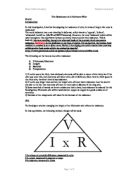
Diagram of a circuit:
Method
After conducting the experiment I had to compose and account of the procedure taken in order to complete it. In order to carry out the experiment the following steps were taken.
- The power pack was set from 2-8 volts and it was switched of while setting up the apparatus just in case there are any injuries.
- 100cm of wire was measured accurately for the experiment so that the test results will be accurate and fair.
- The length of wire was connected to the test gap.
- The voltmeter and the ammeter were then connected to the circuit like the one shown on the last page.
- The variable resistor was changed in every test so that we had different results and not the same. There were three tests. In each test we had to change the resistance.
- The readings from the voltmeter and the ammeter were recorded. These were the readings for the 100cm wire.
- I then switched off the power supply. This as done for safety.
- I measured the wire every 10 cm up to 100cm, writing down the readings from the two digital multi-meters (voltmeter and ammeter).
- The experiment was the repeated three times. Each time the resistance was changed. This gave us three different results for each test.
The Results came out average and I obtained every single reading from the voltmeter and the ammeter.
Analysing the evidence
Conclusion
In the experiment, I found out that as the length of the wire increases, the resistance also increases. This means that as the length of the wire is amplified by 10cm each time the resistance of the also becomes higher.
When the wire was at a length of 10cm the average resistance was 2.65 Ohms. When the wire was lengthened to 50cm, the average resistance rose to 11.22 Ohms. When the wire was increased further to 100cm the average resistance rose to a profound 13.73 Ohms. This clearly portrays that as the length of the wire was increased the resistance, in turn, also increased.
When an electric current passes through thin wire, the electrons cannot flow easily. They collide with atoms in the wire, which makes them vibrate more quickly. If then the length of wire is great then the resistance will be greater.
This information and the trends made visible, in each of the graphs, clearly verifies, my original prediction that as the length of wire increases, the resistance will also increase.
To check the trends encountered, whilst conducting the investigations. They are in the next 4 pages.
Analysing the Evidence
Test 1
Below is the graph that was produced, in order to convey the results from the first experiment, Test 1.
Graph from Test 1
Analysing the Evidence
Test 2
These are the results from the second experiment, Test 2 on a graph. You can see that the results are nearly the same as in Test 1.
Graph from Test 2
Analysing the Evidence
Test 3
The following graph was created after conducting experiment three (Test 3) and conducting the results.
Graph from Test 3
Analysing the Evidence
Average
The average set of results was obtained by adding the resistance for each test and then dividing it by three. This was done for each length of wire; the graph created from the results is shown below.
Average Results
Evaluation
During my investigation I had to set up a circuit. I had to use a 100cm Nichrome wire, a voltmeter, an ammeter and a power supply. Using these, I was required to measure various lengths of wire and record readings from the ammeter and voltmeter.
I found the resistance by diving the volt and the current. As I was measuring the wire, the lengths may not have been correct because the measuring utility was a meter stick. This may have reduced the accuracy of my results drastically. The readings from the ammeter and the voltmeter were precise and very clear.
Improvements
I decided that if I was to carry out the investigation again, I will make several improvements to how the experiment was done originally.
I would use a different measuring device for measuring the length of the wire because the method I was using in the experiment was not a good method and it was hard to get the measurements right for the wire.
I could have recorded the results another two to three times ad this would have gave me accurate results extremely precise.
Reliability of the experiment
To improve the reliability of the results the tests were repeated three times. The three set of results were very similar, if not the same, this confirmed that my results were accurate and reliable. The voltmeter and ammeter had digital scales and therefore giving the exact readings that were extracted without any fault.
Further Work/Improvements
After effectively carrying out the investigation, I was obliged to contemplate the concept of further work. If I could come across the idea at first, I could have done better if I used different wires. Therefore expanding my results and comparing them with the results from a different experiment using a different wire. This would have identified, which wire has the most resistance, when the length is gradually increased.
I could also use thin and thick wires for the experiment which will show that if the wire is thin less current flows through and therefore the resistance will be low. But if the wire is thick, the current will be far greater and the resistance will be greater than before.
Another means of furthering my work will be to investigate the effects of the temperature, on the resistance of the wire. I would have to conduct two experiments for this experiment. The apparatus will have to be identical to conduct a fair test. The difference between both experiments will be by measuring the temperatures, in which the experiments are conducted. This would then let me evaluate on the kinds of temperatures, altering the resistance of the wire.