Seeing how the Length of Wire affects the Resistance to the Current
Nicholas Marshall 11A
Seeing how the Length of Wire affects the Resistance to the Current
Aim-
To see how increasing the length of the wire affects the resistance to the flowing current.
Scientific knowledge-
The things that I need to know about in this experiment are current and resistance.
Current-
In a battery one plate is at a positive potential and the other is at a negative potential, this potential difference being a property of the chemicals of which the battery is made. If a wire joins the battery terminals, the potential difference that exists between the ends of the wire will result in the weakly bound electrons (metals have electrons which are very weakly attached to their atom, which is why they're such good conductors) to flow through the wire. This makes an electric current.
When the rate of flow of a charge past a point is 6 x 10¹⁸ electrons per second, the current is 1 ampere (A).
Potential Difference (Voltage)-
In order to achieve current flow in a circuit a potential difference (V) must exist. The unit of potential difference is the volt (V). Two points are at a potential difference of one volt if one joule of work is done per coulomb of electric charge passing between the points.
Resistance-
Resistance occurs when the electrons travelling along the wire collide with the atoms of the wire. These collisions slow down the flow of electrons causing resistance. Resistance is a measure of how hard it is to move the electrons through the wire. 4 factors affect resistance:
Factor 1: Temperature: If the wire is heated up the atoms in the wire will start to vibrate because of their increase in kinetic energy. This causes more collisions between the electrons and the atoms as the atoms are moving into the path of the electrons with their increased kinetic energy. This increase in collisions means that there will be an increase in resistance.
Factor 2: Material: The type of material will affect the amount of free electrons that are able to flow through the wire. The number of electrons depends on the amount of electrons in the outer energy shell of the atoms, so if there are more or larger atoms then there must be more electrons available. If the material has a high number of atoms there will be high number of electrons causing a lower resistance because of the increase in the number of electrons. Also if the atoms in the material are closely packed then the electrons will have more frequent collisions and the resistance will increase. So in this way, the material can depict whether there will be more or less resistance.
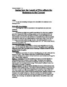
Factor 3: Wire length: If the length of the wire is increased then the resistance will also increase as the electrons will have a longer distance to travel and so more collisions will occur. Due to this the length increase should be proportional to the resistance increase.
Factor 4: Wire width: If the wire's width is increased the resistance will decrease. This is because of the increase in the space for the electrons to travel through. Due to this increased space between the atoms there should be less collisions.
How to measure resistance:
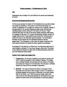
As the potential difference between the ends of a conductor is increased the current passing through it increases. If the temperature of the conductor does not alter, the current that flows is proportional to the potential difference applied (Ohm's law). Here's a graph to show this rule.
The gradient of this graph has a constant value, obtained by dividing the potential difference at any point by the current. The value of this constant gradient is known as the resistance of the conductor. When the line curves you know that temperature is affecting it in some way.
The formula therefore for resistance is: Volt (V) / Current (I) = Resistance (R) (?)
Or
V = I x R
Considering the plan-
For this experiment I already have the processes for measuring the resistance. It includes voltage and current (as seen form the formulas above) so I will need an ammeter and a voltmeter to measure the to values that I need to get the resistance value. I will also need a battery/ power pack to get my current flowing and wires to make the circuit and I also need an ...
This is a preview of the whole essay
The formula therefore for resistance is: Volt (V) / Current (I) = Resistance (R) (?)
Or
V = I x R
Considering the plan-
For this experiment I already have the processes for measuring the resistance. It includes voltage and current (as seen form the formulas above) so I will need an ammeter and a voltmeter to measure the to values that I need to get the resistance value. I will also need a battery/ power pack to get my current flowing and wires to make the circuit and I also need an exposed wire (no plastic coating). This exposed wire will be the wire of which I'll change the length to. I will also need something to connect the exposed wire to the circuit wire so crocodile clips will be used.
The ammeter and voltmeter will have to be placed in specific places within the circuit. I will have to place the ammeter at the beginning of the circuit so that not much wire can resist the current and distort the amp value, because the more wire there is the higher the resistance. Since though I only want the voltage of the exposed wire (not the entire circuit) the voltmeter will have to be placed parallel to the exposed wire. In this way I will only get the voltage of the exposed wire, which is what I want.
Upon consideration I realised that when the length of the exposed wire is changed the potential difference will also change. This means that one of the factors that I need to keep constant, the volts, will change where it's not supposed (which in turn will vary the amps as well). So I need something to control this and a variable resistor works perfectly for it. I will change the voltmeter during a test so that the specified volt reads on the voltmeter.
Plan-
Apparatus:
* Power pack
* Wires
* Ammeter
* Voltmeter
* Variable resistor
* Crocodile clips
* Exposed wire
* Ruler
* Cello tape
Method:
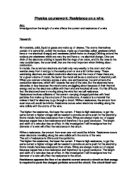
I will first of all set up my equipment. I will gain a power pack and extend a wire from it. At the other end of this wire will be the ammeter with another wire coming out of it from the other side. At the end of the ammeter's other wire is the exposed wire (a crocodile clip will be used to connect the circuit wire to the exposed wire) but there will also be another wire coming from this same wire. This wire that extends from the ammeter's wire connects onto the voltmeter. The voltmeter will have another wire out of the other side of it. This wire from the voltmeter will connect to another wire, and this wire will have a crocodile clip that connects to the other end of the exposed wire. This wire, which has the wire from the voltmeter and connects to the exposed wire, connects to one side of the variable resistor. The other side of the variable resistor has a wire that connects to the other side of the power pack, thus completing the circuit. This is very confusing so I will do a diagram.
Diagram:
Once I have the equipment set up I will tape the either end of the exposed wire, stretching it so that it's straight, to a ruler. In this way I can adjust the length of the wire to accurate readings.
I will then turn on the power pack and move the crocodile clips so that I get the desired length of wire and then adjust the volt to whatever volt I'm doing by using my variable resistor. Once that is sorted out I will record the length of the wire, the voltage and the amp readings. I will repeat this for various lengths and voltages.
Once I have the results I will make graphs (volts by amps) and from the line I will get the resistance by using this formula: V = I x R. The only thing to note is that when I take two results from my graph I will have to make sure that they are proportional. To do this I will choose a voltage result and create a straight horizontal line on that graph from the chosen value to the line of best fit. When the line reaches the line of best fit I will stop going horizontally straight and instead go vertical straight downward. Where this line ends up on the amp axis is the amp value that is proportional to the earlier chosen volt value. These two values will be used in my formula to get the resistance value.
Once I have all the resistance values for every length measurement of wire I will create another graph of the resistance by the length of wire. It is this graph that will answer my aim.
Fair Test-
To make this a fair test I will have to keep everything constant within each test.
This includes keeping the length of the wire the same within a test (although the lengths will vary from test to test), keeping the voltage the same within a test (this may require moving the variable resistor and the voltage will vary also from test to test), keeping the same wire (as the materials may vary and, as said in the scientific knowledge, different materials may result in different resistance), keeping the temperature constant as it affects the resistance and keeping the width of the wire the same. You might have noticed that I have mentioned the 4 factors that affect resistance that were said within the scientific knowledge. I have to keep these the same otherwise my results will get distorted. The reason why they get distorted is explained within my scientific knowledge.
Prediction-
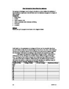
I predict that, from my scientific knowledge, the amps will be proportional to the voltage. This is because the voltage is the source where the electrons are from. The bigger the voltage the more electrons there are and so the bigger the current. I say that it will be proportional because the two values are directly linked and so if one goes up the other will also go up. Here's a prediction of my graph.
I also predict that as the length of the wire increases so does the resistance. This is because as the wire increases in length so does the number of atoms of the wire. This increase of atoms means that there will more collisions with the electrons that form the current and so in this way resistance will increase. Here's a prediction of my graph.
Preliminary Test-
Within this test I plan to find out the range of the lengths of the wire and of the voltage. To find out the range of the lengths I will keep the voltage constant within the test and find out what the amp values are for a low length measurements value a high length measurements value. If I think that there is a big enough gap between the 2 amp results to get enough other results between them to see an easily recognisable pattern then I will have them as my highest and lowest length values and use logic to find out what range I will have between each other length value.
For the voltage test I will do exactly the same as I have sad above except I will have the length measurement as a constant and choose a high and low volt value.
Preliminary test to find the range of the wire length measurement values-
Since I will be working with metre ruler sticks my highest value will be 100 cm and my lowest value will be 10 cm. If there is a sufficient gap between the 2 amp results to make a recognisable pattern then I will have a range of 10 cm between each length measurement, which will give me 10 results for every volt I do. The volt I choose is 2. This value will be kept constant and is a random choice.
Wire length (cm)
Voltage (V)
Current (A)
0 cm
2V
.99 A
00 cm
2V
0.23 A
I think that there is a big enough gap between the 2 current results to get a recognisable pattern. So as I said before I will have 10 cm as my lowest value and 100cm as my highest value and will have a range of 10 cm between each length measurement (so 10cm, 20cm, 30cm, 40cm, 50cm, 60cm, 70cm, 80cm, 90cm, 100cm).
Preliminary test to find the range of the voltage values-
The highest voltage that the power pack can take is 5 volts, but it keeps cutting out on that value so my highest value will be 4 volts and my lowest will be 1 volt. If there is a sufficient gap between the two amp results then I will have these 2 volt values as my highest and lowest values and there will be a range of 1 volt between each volt value. The wire length I choose will be 50cm. This value will be kept constant.
Wire Length (cm)
Voltage (cm)
Current (A)
50cm
V
0.22
50cm
4V
0.88
I believe that 2 other results could be spread quite well between the two amp values and a recognisable pattern could be seen. So I will keep 1V and 4V as my highest and lowest values and the range will also be 1 volt between each value (so 1V, 2V, 3V, 4V).
I think that to get even more accurate results I will repeat each test twice and then make an average from the 2 results. This way the repeated value will dim any abnormalities in the other value.
Experiment-
When doing the experiment I will apply all that I've said and be very accurate when setting up and doing the tests. In this way I will get really accurate results.
Results:
Wire length (cm)
Voltage (V)
Current (A) 1st repeat
Current (A) 2nd repeat
Current (A) Average
0 cm
V
.02 A
.00 A
.01 A
20 cm
V
0.51 A
0.55 A
0.53 A
30 cm
V
0.36 A
0.36 A
0.36 A
40 cm
V
0.25 A
0.27 A
0.26 A
50 cm
V
0.20 A
0.23 A
0.215 A
60 cm
V
0.18 A
0.18 A
0.18 A
70 cm
V
0.17 A
0.13 A
0.15 A
80 cm
V
0.14 A
0.12 A
0.13 A
90 cm
V
0.11 A
0.13 A
0.12 A
00 cm
V
0.11 A
0.11 A
0.11 A
Wire length (cm)
Voltage (V)
Current (A) 1st repeat
Current (A) 2nd repeat
Current (A) Average
0 cm
2V
2.01 A
2.02 A
2.015 A
20 cm
2V
.06 A
.06 A
.06 A
30 cm
2V
0.68 A
0.72 A
0.70 A
40 cm
2V
0.52 A
0.54 A
0.53 A
50 cm
2V
0.45 A
0.43 A
0.44 A
60 cm
2V
0.36 A
0.36 A
0.36 A
70 cm
2V
0.31 A
0.33 A
0.32 A
80 cm
2V
0.24 A
0.28 A
0.26 A
90 cm
2V
0.24 A
0.24 A
0.24 A
00 cm
2V
0.22 A
0.22 A
0.22 A
Wire length (cm)
Voltage (V)
Current (A) 1st repeat
Current (A) 2nd repeat
Current (A) Average
0 cm
3V
3. 08 A
3.00 A
3.04 A
20 cm
3V
.61 A
.59 A
.60 A
30 cm
3V
.11 A
.11 A
.11 A
40 cm
3V
0.79 A
0.81 A
0.80 A
50 cm
3V
0.69 A
0.69 A
0.69 A
60 cm
3V
0.50 A
0.56 A
0.53 A
70 cm
3V
0.45 A
0.47 A
0.46 A
80 cm
3V
0.38 A
0.36 A
0.37 A
90 cm
3V
0.36 A
0.36A
0.36 A
00 cm
3V
0.33 A
0.33 A
0.33 A
Wire length (cm)
Voltage (V)
Current (A) 1st repeat
Current (A) 2nd repeat
Current (A) Average
0 cm
4V
4.05 A
4.03 A
4.04 A
20 cm
4V
.97 A
.97 A
.97 A
30 cm
4V
.37 A
.41 A
.39 A
40 cm
4V
.08 A
.07 A
.075 A
50 cm
4V
0.87 A
0.87 A
0.87 A
60 cm
4V
0.71 A
0.74 A
0.725 A
70 cm
4V
0.59 A
0.60 A
0.595 A
80 cm
4V
0.53 A
0.52 A
0.525 A
90 cm
4V
0.50 A
0.46 A
0.48 A
00 cm
4V
0.43 A
0.43 A
0.43 A
Graphs:
Please Turn Over
Analysis of Graphs-
All the graphs have a straight upward line of best fit and all the points fit well into the line. This includes the resistance graph.
Conclusion-
First of all lets remind us of my experiment aim; 'to see how increasing the length of the wire affects the resistance to the flowing current'. My answer to that, by looking at my last graph, is that as you increase the length of the wire the resistance also increases in a proportional way.
All my predictions were proved right. My first prediction was that the bigger the voltage the bigger the current. I also said that those two values would rise in a proportional way. Both these predictions were proved to be right as the volt by current graphs showed me that the current did rise with voltage. My predicted graph is also proven right by comparing it to my graphs from my results as they both have straight upward lines to show that as the voltage increases so does the current.
The reason behind this happening is because the voltage is the source where the electrons are from. Therefore the bigger the voltage the more electrons there are and so the bigger the current. Since they are directly linked then they will be proportional.
The second thing that I predicted was also proven right. This was that as the length of wire increases so does the resistance. My predicted graph was also a straight upward line showing how the resistance increases with the length of wire. I was proved; again, right because if you look at my last graph they do show that as the length of the wire increases so does the resistance. My predicted graph is also proven right by its connected graph because they are similar.
This is because as the wire increases in length so does the number of atoms of the wire. This increase of atoms means that there will more collisions with the electrons that form the current and so in this way resistance will increase.
Evaluation-
Analysis of method and results-
I am pleased with my method because it turned out accurate reliable results that answered my aim.
Observations-
The main thing that I noticed was that as the wire got shorter the temperature of that wire rose. To compensate for this we had to take down the results very quickly on the shorter lengths and then turn of the power pack and wait for the temperature to return to normal (this took a couple of minutes). I am only mentioning it because it was the main thing that could've distorted my results.
Changes that would be made if I were to repeat the experiment-
If I were to do this experiment again I would take note of the heat problem and perhaps get a 2 metre ruler stick and start on 1 metre instead of 10cm. The only thing that this would show me is if my current results are distorted.
The reliability of my results-
I think that my results were very reliable. This is especially evident in my graphs where the results fit very well with the line of best fit. The fact that everything was based on proven science shows how accurate and reliable my results must be.
Do my results support a firm conclusion-
I think that I had enough results to make a firm enough conclusion on this experiments aim. This is shown by the way that my aim was answered very specifically.
Further work to prove my conclusion-
To improve on this conclusion I could take down more results by increasing the range of the wire length or the volts. Otherwise though the conclusion has already been explained explicitly.
What I could is investigate though is how the other factors of resistance (temperature and width and material of the wire) affect resistance. The experiments would be quite similar but the length would no longer be a variable. This would give me a broader view and idea of resistance.
Overall though I think that this was a very successful experiment and that I have managed to gain and analyse some useful results that told, explained and answered me a lot. I have also set myself some more questions for me to answer in any other extra experiments that I may do in the future.