A Stand is used in my investigation to hold the clamp and the electromagnet off the ground. This enables me to add 100g and 10g weights on without them touching the floor.
I am using a Clamp to attach the electromagnet to the stand securely.
2 Connector wires are needed to supply the electromagnet with the voltage it needs to lift the weights.
The Power Pack is to supply the voltage to the electromagnet.
Crocodile clips are used as they can connect the connecting wires to the one wrapped around the electromagnet
Weighing scales are needed to weigh the magnet, which is attached to the main electromagnet after the experiment.
Weights (10-100grams) are needed as a form of actually measuring how much the electromagnet can hold.
Wire (to coil around the electromagnet) is used to make the magnet an electromagnet.
Safety
I will make sure that there is no water near any electrical equipment. This will prevent electrocution. I will also place tissue paper underneath the electromagnet so that if any of the weights or the electromagnet itself did fall down it would stop it from chipping the table or floor. Whilst the experiment is being carried out I will make sure I do not leave it unattended in case an accident with the electromagnet occurs. I will also place the clamp on the stand as close to the ground as possible. That way I can ensure that if the electromagnets and weights do fall then they will not have that far to fall. Therefore there is less chance of myself being injured or the table below getting damaged.
Range of Observations
I will make my observations using the following numbers of coils around the electromagnet. The voltage of 3 volts will remain constant though out.
5
10
15
20
25
30
35
40
45
50
I will repeat the procedure three times for each number of coils and then work out an over-all average of my results. This will give me a much more accurate and reliable result. My investigation will be accurate within 10 grams, as 10 grams is the smallest weight that I will use in my experiments. This is quite a high level of accuracy.
Preliminary Work
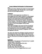
Before I carried out my main experiments I carried out some preliminary experiments. I tested to see how many coils I could wrap around the electromagnet so that they were still evenly spaced along it. The most I could accurately get was 50 turns. Below in diagram A is the first layout I tried.
I realised that this did not work because the tin was too weak to support such a large amount of weight. So I used a 100g weight as its shape enabled the hooks to stay more balanced, as shown in diagram B above. This worked well as the 100g weight could support the other weights and wouldn’t fall. I tried other set ups but the one shown in diagram B worked the best.
I tested 10 turns of the electromagnet with 5 volts from the power pack. It held roughly 700g altogether. This was too much weight as when I had more turns of the coil on the electromagnet the amount of weights needed would increase so much that it would become unsafe and inaccurate. In my main experiment, therefore, I will only use 3 volts on the power pack. This way I can gain a wider and more accurate range of results. One more thing that I noticed from my preliminary results was that where possible my investigation will be safer the closer the clamp is to the table. That way it has a shorter distance to fall and there will be less chance of any damage.
Obtaining Evidence
Results
Below is a table showing number of coils against total mass held. I have worked out my averages to one decimal place, as my results were no more accurate than that. It is also makes the average a sensible number to plot accurately on a graph.
Analysis and Conclusion
On the next page there is a graph to show the number of coils against mass held (grams) show me a curve which I can successfully conclude and analyse from.
Just by looking at my graph I can say that the first prediction that I made has been proved as the number of turns increases as the mass lifted does. I have divided my graph into 3 sections and have shown the gradient of each section below.
Section 1 (0 to 4 coils) = gradient of 21.68
Section 2 (4 to 16 coils) = gradient of 125.00
Section 3 (16 to 20 coils) = gradient of 584.93
I can tell also, from my graph that the magnet strength increases as the number of coils increases. My graph can be split into three distinct sections. The first section contains my first two results (2 and 4 coils). The graph increases at a steady rate in this section.
The next section is includes 8 to 16 coils. In this section the gradient gets a lot steeper than it was previously at a gradient of125 and after that (18 and 20 coil section) it increases yet again to a gradient of 584.93.
Form this graph that it is not a straight, directly proportional line like I expected in my prediction. In fact the results tend to increase exponentially. Therefore my prediction has been proved to be incorrect.
Evaluation
Some of my results may have been inaccurate due to the iron core being magnetically saturated. This means that the magnetism could not get any stronger. This was probably the case in my experiment as I did the experiments one after another. Although the resistance of the wire would have probably have played some part in it as well. Any resistance in the wire would cause the wire to heat up and would therefore destroy the magnetism.
If I were to do this experiment again I would try and do it with a wire that had the lowest resistance possible. However I do think that in most respects my experiment was a fair one as far as possible. I made sure that my experiments, in fact my whole investigation was a fair one by setting aside the wire and electromagnet. It was important to use the same wire throughout, as all the wires would have had a varying resistance. The electromagnet would need to stay the same as all electromagnets have varying iron u-core strengths, which would affect my results if varied.