For this experiment the factor that will be investigation is the ‘length’. This is because if the cross-sectional area was the factor under investigation different diameters of the wire would be needed and would need to be specially ordered by the school, the school has a limited supply of different types of wire which all have the same diameter. The length will also be much easier because by just moving the position of a crocodile clip can easily vary the variable.
In the investigation the results that will be found will be the current, which is measured by an ammeter, and the potential deference, which is measured by a Voltmeter. The resistance can then be calculated by using ‘Ohm’s Law’:
V = I .R
Or
R = I
V
Preliminary work
The aim of the preliminary work is to find a good range of current values. This is because if the current is too high then a lot of heat is produced which will change our results and make the experiment an unfair test.
In order to find a good range of current values a suitable voltage must be found and a suitable range of the wires length must be found.
A suitable voltage is one that is small enough to keep the temperature constant and a voltage large enough to be able to produce a large enough range of figures so that the ammeter can produce a difference in the results.
A suitable range for the length of wire would be that the ammeter is able to recognise a difference in the readings, and the length isn’t too small because it will increase the current and the temperature will rise and that the length isn’t too large so that it is recognised that an ammeter has been used.
Previously it has been found that the temperature stays quite constant between 0.1A and 1.0A. This then means that the preliminary work should aim to find the velocity and a length so that the current range is between 0.1A and 1.0A.
Preliminary Method
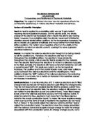
- Set-up the circuit as shown below.
- Connect the circuit to a 1.5V Battery.
- Measure the current and voltage for every 10cm of wire.
- Repeat, but measure the current for 90cm of wire.
- Calculate the resistance using Ohm’s Law (V = IR).
- If necessary, repeat steps 1-5 using 2 x 1.5V batteries.
- Repeat again, if necessary, to get a suitable range of currents, using wire lengths of 20cm/30cm/70cm/80cm.
(It maybe necessary if the current is too high at a certain length.)
Diagram
Preliminary results.
Preliminary Conclusion.
From these results it is evident that two 1.5 Volt batteries should be used because they produce the desired range of current. However, when the length of wire is 10cm the current is too high because the temperature of the wire increased instead of staying constant. Therefore the range of the lengths in the investigation is 20cm to 100cm.
These results conclude that to produce the desired range of current values the voltage of two 1.5V batteries should be used on the lengths of wire 20cm – 100cm.
From the preliminary work it has also come to the attention that the current should be on at a minimum, i.e. short periods of time, to keep the temperature of the wire constant.
Prediction
I predict that as the length of the wire increases the resistance will increase. I also predict that the length of the wire will be directly proportional to the resistance:
R α L
Scientific reasoning
In the introduction it has already been stated that as the length of a resister is increased the resistance increases. This is because the ions in the resistor are the particles that oppose or resist the flowing of the electrons because the outer-shell of the ions are negative electrons they repel other particles of the same charge i.e. the negative valence electrons. Thus if the length of the resistor increases then the number of ions increase. The only channels for the valence electrons to flow though are the gaps between the ions.
The shorter the resistor the less times the electrons is knocked off course, which lowers the resistance because the electrons pass through the resistor quicker.
The longer the resistor the more times the electrons are likely to be knocked off course which increases the time the electrons flow through the resistor and thus increases the resistance.
We can also put into context that if you double the amount of ions, by doubling the length of the wire, then you double the resistance because the number of obstacles (ions) is doubled. If you go to the next extreme, if you triple the length of wire then the resistance is tripled. From this theory we can derive:
Resistance is directly proportional to Length.
R α L
Apparatus
- 1.5V Batteries x 2
- Electronic Ammeter x 2
- Electronic Voltmeter x 2
- 1m ruler x 1
- 1m Constantan wire (0.02 diameter)
- Sellotape
- Electrical leads x 6
- Crocodile clips x 2
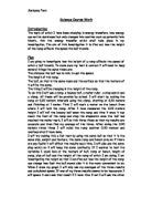
Diagram
Circuit Diagram
Method
- Set-up apparatus as shown above in the diagrams. There must be a gap in the circuit so it can be turned on and off.
- The Constantan wire show be sellotaped taut again the ruler and that the wire spans the whole length of the ruler.
- Connect one crocodile clip on the wire at the 0cm mark on the ruler.
- Connect the second crocodile clip at wire on the 100cm mark.
- Connect the wires to the 2 x batteries so that a full circuit i.e. a current flow is flowing.
- Record the current using the ammeter.
- Record the potential difference across the wire using the voltmeter.
- Disconnect the wires from the batteries as quickly as possible so that the circuit is broken.
- Then repeat points 4-8 but this time change the length of the wire by moving the second crocodile clip (at point 4) to 90cm and then decrease the length of the wire until the length of the wire is 20cmm in 10cm intervals.
- Repeat point 4 –9 once.
- The table of results should then have nine lengths of wire with an average voltage and current for each length.
- Calculate the resistance by using Ohm’s Law. (The figure used in calculating the resistance are the average) Ohm’s Law states: Ohm’s law states that: “the current flowing through a metal wire is directly proportional to the potential difference across it, providing the temperature remains constant”. We can derive the equation: V = IR. This equation can then be re-arranged to find the resistance of the wire. Rearranging the equation we get: R = V/I.
Fair Testing
In order to make this experiment a fair test the only variable that will be changed is the length of the wire. This means that the other variables that can change the resistance of a wire must be kept constant. These other variable s are:
- Cross-sectional area of the wire (0.02mm)
- Material (Constantan 36 SWG)
(The voltage does not need to be kept constant but to be able to calculate the resistance of the wire it must be measured at each length because Ohm’s Law is true providing the temperature is constant.)
Safety
- Ensure that all connections are secure before the power is switched on.
- Do not touch the wire being used as a resistor until after the power has been turned off. It is recommendable not to touch the wire for a short while after the power has been switched off because the wire may be hot.
- Ensure that the work area is dry because water is a very good conductor and could cause electrocution.
- Take care when using scissors to cut the wire/sellotape.
- All accident must be reported to the teacher immediately.
Conclusion and Graph
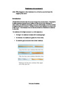
It was previously predicted that the greater the length of wire the greater the resistance. I also predicted that the resistance of the wire was directly proportional to the wire’s length. The graph produced from the averages of the resistances obtained in the experiment proves the prediction because in the graph a straight-line through the origin was produced.
The graph plotted was Resistance versus wire length graph (R against L) therefore the resistance is directly proportional to the length of the wire (R α L), as predicted in the prediction.
The prediction predicted that the greater the length of wire the greater the resistance. The resistance will be greater because, in longer wires, electrons have the pass more ions (opposition) when travelling through the wire. This means that there is a greater probability that an electron will collide with an ion.
The more collisions the more times an electron is knocked off course and thus more time to travel through the material.
Using this theory, it seems that the resistance of a wire can be quantified, because it seems that if an electron has to pass twice as many ions as in the original wire then the electron will collide with twice as many ions and will, consequently knocked off course twice as many times with the result being that the electron takes twice as long to travel through the wire.
Doubling the length of wire doubles the number of ions in the wire and therefore it will take an electron twice as long to go through a piece of wire twice as long. In a similar manner, it will take an electron three times as long to travel through a wire three times as long.
This can then be applied to a piece of wire ‘x’ times as long as the original wire because we can see that it will take an electron ‘x’ times as long to pass through a wire ‘x’ times as long (on average).
Thus, we can deduce that:
R = x L
(‘x’ is a constant)
Evaluation
The think that the experiment performed was successfully as there were no anomalous results plus the results produced a perfect line of ‘best-fit’. The fact that there we no anomalous results shows that the method was suitable and was carried out accurately. It also suggests that the points mentioned in the preliminary work - regarding leaving the power supply on for the minimal time to keep the temperature constant which achieved accurate results and suggests that the choice of voltage and wire lengths was made successfully.
However, some slight inaccuracies did occur in the experiment and this led to a line of ‘best-fit’ i.e. there was not a straight-line joining all of the points together being drawn. The inaccuracies it seem could have been attributed by the following:
- Inaccurately judging the wire length, the length of wire may have been slightly inaccurately judged because judging the wire to be completely straight and taut using just our eyes was extremely difficult.
- Temperature change - this variable was the most difficult to keep constant and it seems that this variable was, in fact, not kept constant. It seems that the wire will heat up as soon as the power is switched on and current is allowed to flow because, as soon as the electrons start colliding with the ions in the wire, the wire gains internal energy. Thus, it seems that, as soon as the power was switched on, the wire began to heat up, however slightly. Thus, whilst the temperature rise was kept as negligible as possible by leaving the power switched on for the minimum possible time, it seems that the temperature would have risen and this factor may have affected the results.
- Meters, the ammeter and voltmeter used measured the current and volt across the wire to the degree of one hundredth of an amp and volt, respectively i.e. the current and voltage measurements may be inaccurate by the degree of up to, one hundredth of an amp/volt. Similarly the resistance values calculated from the current and voltage measurements may be slightly inaccurate.
- Contact with crocodile clips, this factor may have affected the accuracy of the results, but this is extremely unlikely as it was ensured that the crocodile clips made definite contact with the wire being used as a resistor.
These factors may have produced extremely slight inaccuracies and the results were only slight inaccurate and so it seems that the minor inaccuracies that the above factors may have caused may have caused the results in the investigation to be slightly inaccurate.
Further work in the experiment could be to find the resistance of the Constantan wire used in the experiment.
To find the resistance of the wire we need the two equations below, which were found from extra research. The equations tell us that the resistance of a wire is:
-
Directly proportional to its length (L) i.e. R α L
-
Inversely proportional to its cross-section area (A) i.e. R α 1/A
Combining the two statements we get:
R α L x 1/A
The above can then be written as an equation if we insert a constant:
Therefore, R = x L/A
Where ‘x’ is a constant called the resistance of the material (for a fixed temperature and other physical conditions).
“The resistance of a material is numerically the resistance of a sample of unit length and unit cross-section area, at a certain temperature.”
To find ‘x’ we can rearrange the equation “R = x L/A” to get “x = AR/L”. Thus, to find the resistance (x) of the Constantan wire used in this experiment we must substitute for A, R and L in the equation x = AR/L.
- The wire being used in the investigation should have a uniform cross-sectional area, but, to confirm this, the diameter of the wire can be measured using a micrometer. In this investigation the diameter of the wire was 0.02mm and so the cross-sectional area of the wire can be estimated, by assuming the wire’s cross-section is circular, using the equation:
Cross-sectional area = πr2
Where ‘r’ is the radius of the circular cross-sectional area, which is half of the diameter
- Other ways to further the experiment would be to use wires made from different materials to find differences in resistance that each wire produced. It could then be decided which of the wires was the best conductor.
Cross-sectional area could also be investigated, if the experiment was furthered, and it could be investigated whether the resistance of a wire is inversely proportional to its cross-sectional area. To investigate the effect of cross-sectional area on resistance of similar wires (i.e. wires of the same length, material, etc.) with different cross-sectional areas will be used.
- The effect of temperature on a wire could also be investigated.
I believe that the experiment was performed successfully and that the results obtained were accurate.
The predictions that were made were also confirmed by the results and the wire obeyed the rules that it was expected to.This experiment we can confirm that the resistance of a wire is directly proportional to the wire’s length.