Width of wire
The width will be measured in swg (single width gage).
28 the thickest wire
30
36 the thinnest wire
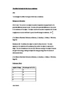
Thick wires let the electric current through easily than thin wires.
e- Thin wire – Not much space, high resistance
e- When the electrons try to move they collide
With each other because they cannot go in any
Direction.
e- Thick wire – More space, low resistance
e- The electrons can move freely in any
e- Direction and so they will not collide as much
e- Allowing them to move through quicker.
Length of wire
As the wire length increases, so will the number of ions that must be passed by the electrons. This causes more resistance as the electron have further to travel in the wire. On the other hand, as the wire length decreases, fewer metal ions must be passed and the resistance becomes lower. This means that current flows more easily.
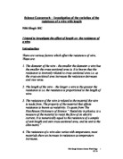
Type of metal
The type of metal I will be using will be an alloy. Some metals may have less electrons flowing quicker, meaning there is less resistance or some metals may have more electrons causing more resistance due to more electrons colliding. For example, copper has less resistance. Copper has 2 electrons.
Prediction
After considering all the variables I have come up with a number of predictions.
I think the longer wire, the electrons have further to travel, and is made more difficult for the electrons to travel. The electrons would collide into the vibrating atoms causing the electrons to slow down. This would mean there is more resistance. Therefore as the wire gets longer, there will be more resistance. The shorter the wire, the less resistance as electrons have little to travel and have less atoms to pass and therefore the shorter wires will have less resistance.
As the wire is thicker there will be less resistance meaning the electrons can travel freely so I predict the 28swg will have less resistance as it the thickest of the three wires that I will be testing. Although the thinner the wire, there will be more resistance as the electrons would collide with each other. I think the alloy I am using will make an impact on the flow of electrons.
While carrying out the experiment if the temperature rises it will affect the movement of electrons causing there to be more resistance. However if the temperature decreases the atoms would not vibrate as much allowing the electrons to flow easily causing there to be less resistance.
I think that the metallic bonding theory will take place in the wire. As the metal cations and the electrons are oppositely charged, they will be attracted to each other, and also to other metal cations. I predict the tighter the hold on the electrons the higher the resistance.
I predict as I double the length of the wire the resistance will also double. I will see if my prediction is true when I conclude my results.
Pre-test
Aim: To see how the width affects resistance
Method: I will now carry out a pre-test to help me choose a suitable width for the wire. I will setup the equipment correctly. I have used two different lengths, 20cm, the minimum length and 100cm, a maximum length. I have used two different input volts, 1 a minimum volt and 5 a maximum volt.
Looking at my table, the results are very low at 1 and 5 making it difficult for me to choose a suitable wire width. I will redo my pre-test and will change the voltage to 3 & 7
The best width for the investigation would be 28 swg because it has the highest current which means there is less resistance. This would be the most suitable wire width.
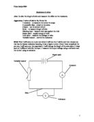
The experiment
Method: First I will set up the apparatus making sure the wire is smooth and taut. I will alter the length of the wire to 20cm, making sure that it is taut so that it is accurate. I will measure the voltage and current at 3 volts and then 4,5,6 and 7. To make the experiment accurate I will turn off the power pack once I have a reading for the current and voltage. I will alter the length to 40cm and measure the voltage and current at 3,4,5,6, and 7. I will repeat this for the lengths 60cm, 80cm and 100cm. From these results I will calculate the resistance using the ohms law – resistance = voltage/ current. I will then find the average of the readings of each length. I will plot these readings on a graph. These reading should tell me how the length of the wire affects the resistance. I must consider safety. If the power pack is left on for too long, the wire will heat up.
Results
Safety: Turn off the power when adjusting the power pack. Make sure all the wires are insulated except the wire that is being tested. I must make sure the power pack is not left on for too long as this could cause the wire to heat up which would be unsafe. I will make sure the equipment is set-up away from water.
I had one anomalous result at 2.1, which I have circled in the 80cm readings at 6 volts. This could of happened for many reasons. I measured the anomalous results from a 1.0 range.
Precision
We measured the wire accurately by holding it taut and then we measured it by using the masking tape. I held it against the ruler and taped it to the ruler still allowing us to move the crocodile clip to the different points. The current was measured to a 1/100 of an amp to 2 decimal places. The voltage was measured to 1/100 of a volt to 2 decimal places. When carrying out the experiment, I placed the crocodile clips exactly on the point.
Analysis
I have created a table from my results:
I have calculated an average of the four numbers, eliminating the anomalous reading
I have created a graph to show my results. I have also created a graph to show how the resistance increases as the current increases. From these graph I have calculated the gradients.
Resistance at 20cm
Y = mx + c c = 0
M = y2 – y1 = 0.35 – 0.35 = 0 = 0ohms voltage = 0 x current + 0
x2 – x1 = 0.10 – 0.10 0
Resistance at 40cm
Y = mx + c c = 0
M = y2 – y1 = 0.54 – 0.18 = 0.36 = 1.8 ohms voltage = 1.8 x current + 0
x2 – x1 = 0.30 – 0.10 0.2
Resistance at 60cm
Y = mx + c c = 0
M = y2 – y1 = 0.85 – 0.17 = 0.68 = 2.72 ohms voltage = 2.72 x current + 0
x2 – x1 = 0.30 – 0.06 0.25
Resistance at 80cm
Y = mx + c c = 0
M = y2 – y1 = 1.23 – 0.20 = 1.03 = 3.8 ohms voltage = 3.8 x current + 0
x2 – x1 = 0.33 – 0.06 0.27
Resistance at 100cm
Y = mx + c c = 0
M = y2 – y1 = 1.44 – 0.40 = 1.04 = 4.3 ohms voltage = 4.3 x current + 0
x2 – x1 = 0.33 – 0.09 0.24
Resistance as the length increased
Y = mx + c c = 0
M = y2 – y1 = 4.3 – 0.8 = 3.5 = 4.37ohms voltage = 4.37 x current + 0
x2 – x1 = 0.95 – 0.15 0.8
Conclusion
Looking at the graph I can see as the length of the wire increased so did the resistance and it is at a constant rate. This relates to the theory where as the wire gets longer, the atoms are vibrating making it harder for the electrons to flow causing more resistance. This agrees with my prediction, as I did believe that the longer the length the more resistance there would be.
I chose to use the 28swg width wire which I had tested before. From that pre-test the 28swg wire was the thickest and the theory was as the width of wire increases, the less resistance there is, as the electrons are able to move freely. I think there was less resistance as I had chosen to use a wire width less resistance. Here I have proved my prediction as shown on the results graph.
The temperature did have an impact on the results. The temperature was obviously not constant during the experiment as the results did fluctuate a lot. This may have happened for many reasons. The opening and closing of doors may have caused a breeze making the wire cooler where the resistance would decrease. Another possible reason there was a change in temperature could be due to not being able to turn off the power pack straight away causing it to heat up where resistance would have increased. I would of like to have known the exact reasons for the change of temperatures through out the experiment as it could have been prevented.
Metallic bonding obviously did take place which is as the metal cations and the electrons are oppositely charged, they are attracted to each other, and also to other metal cations. The electrons moved freely within molecular orbitals, so each electron detaches from its parents atom. There was a looser hold on the electrons in the alloy I tested meaning there was less resistance. My prediction was incorrect.
I made a prediction which was as the length doubles so will the resistance. I looked at the table with the average resistance for each length. I looked at the average for 20cm which was 0.94ohms and doubled it which gave me an answer of 1.88ohms. I then looked at the average resistance for 40cm (double 20) which was 1.79ohms. The results are quite similar as there is only a 0.09 difference between the two. To see if this pattern occurred with the other results, I tested it with another length, 40cm. Again I found the average resistance for 40 cm which is 1.79ohms and doubled which gave me an answer of 3.58ohms. I then looked at the average resistance for 80cm (double 40) which was 3.71ohms. Again the results are quite similar as there is a 0.13 difference between the two. So there is a pattern which I proved.
Overall I think the experiment was quite successful but I think I could have prevented some small problems such as the temperature changing
Evaluation
I think my method was fair because throughout the experiment, the width of the wire was the same at swg. The voltage inputs for each length were kept the same at 3, 4, 5, 6 and 7 volts. The material we used was an alloy which is a mixture of metals. All the equipment I used was not altered. The power pack, volt meter, ammeter, wire etc were kept the same.
My results were quite accurate. The graph where I have plotted resistance against length shows this. I can put a straight line through my graph showing that the increase rate was constant. Looking at my graph, at about 80cm, the resistance is a bout 2.75ohms. The results show that as the length of wire increased so did the resistance.
I had one anomalous result which was where the current was 0.30 and the voltage was at 0.63 which gave me a resistance of 2.1ohms which is an outlier in the 80cm length readings (see graph).
I think I got an anomalous result for a couple of possible reasons. While taking the reading, the temperature may have risen causing the result to change where the resistance would increase or the wire could have been hot from previous reading. I may have left the power pack on for too long causing the reading to change. There may have been a fault in the circuit causing the reading to change. The length of wire may have been affected because the crocodile clip may have moved a couple of millimetres to the left or right which would make the test inaccurate.
I think I could have improved my method by turning the power pack off straight after I had a reading on the ammeter. I could have checked the temperature using a thermometer at regular intervals to making sure it was the same throughout the experiment. The crocodile clips and wire could have been sanded down, getting rid of any excess rust so that it can make connections clearer.
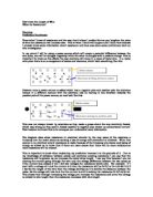
I could have made the readings more accurate by holding the wire taut. I think I could have attached the wire more accurately. The width of each crocodile clip was 4mm. Two crocodile clips would have been attached to either side exactly on actual length. I could have attached both clips exactly either side of the wire as shown below.
4mm 20cm 4mm Crocodile clips (4mm width each)
Wire. e.g. 20cm length. Make sure
Clips are on either side of the wire.
I had five readings for each length. From these results I created a table where I plotted the current against voltage. The line of best fit shows me the rate of resistance and how it increased. I think I could have tested other lengths such as lower and higher numbers such as 5cm or 2 metres.
In addition I could have used an ohmmeter, which measures the resistance. This would be a much better way of measuring the resistance. I think I could explored a wider range of widths, some extremely thick widths or very thin. I would compare this to my present results and see if the readings are drastic. I think I could have tested other materials such as copper. If I were to carry out the experiment using the copper wire instead of an alloy I would expect there to be less resistance. I would keep all the equipment the same as what I used for the alloy to keep the test fair. Another way of making the experiment more accurate is by using a multimeter. By using a multimeter the contact with the wire is less than one millimetre where as the crocodile clips have a contact of 4mm on either side. The length would therefore be measured more accurately. An advanced method of keeping the temperature constant would be using an oil bath. If I were to carry out the experiment again I would submerge just the wire itself into oil which would keep the temperature the same.