- WIRE LENGTH
The longer the wire the greater the resistance is. This is because the longer the wire, the larger the number of atoms, so the more the chance of collisions, which slows down the electrons, and so larger the resistance. If all other factors were kept constant, then we would see that wire length and resistance are directly proportional; if we were to double the length of a wire, then double the number of atoms for the electrons to collide with, and thus double the resistance.
- CONDUCTOR MATERIAL
Material type will affect the resistance. Many elements within different materials can affect resistance, such as the higher the level of impurity, the greater the resistance. But in particular: the density of the material, and the number of free electrons within it. If a material is very dense the resistance will be high, as the collisions will be more frequent, as there will be less space for the electrons to move past the vibrating particles.
THE EQUATION
The equation R=V/I mean that as resistance increases, voltage will also increase; yet current will decrease.
Using this scientific knowledge I may construct the following hypothesis:
HYPOTHESIS: Resistance will increase proportionally with length.
PREDICTED GRAPH:
This is the predicted graph showing wire length in comparison to resistance. It is clearly proportional as wee see a straight line graph that passes through the origin.
VARIABLES:
- Temperature
- Wire diameter
- Wire material
- Voltage
- Wire length
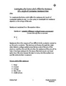
Dependent/Independent?
An independent variable is one that being changed throughout, and is independent of other factors. It is shown on the x-axis of the graph. In this case, it is wire length. The length of wire will be increased by 10cm intervals, and each new length tested. This is done to test how resistance changes with length. If random, unmeasured lengths were tested, then the results would become redundant, as there would be no results to test the hypothesis.
A dependent variable is one that relies on a number of other factors. It should however only rely upon the independent to make it a fair test. In this experiment the dependant variables are all the other factors that may affect the resistance in a wire.
The following variables are all dependants and are therefore acknowledged, and controlled in order to conduct a test where the only change in results will be due to the change in wire length.
Temperature:
The temperature (as stated earlier) will affect the resistance in a wire, as the higher the temperature the more the atoms of the wire will be vibrating making collisions more likely and more frequent. As the particles collide with the atoms the atom gains more kinetic energy and vibrates more, raising the temperature of the wire, and therefore the chance of collision. The experiment will be done in a room where the temperature is constant. The temperature of the wire itself will increase with the length of time that current passes through it, thus we must take the very first reading we are given. The wire must then be allowed to cool, so that it is the same temperature that all the experiments are conducted at.
Wire diameter:
Wire diameter as stated earlier will affect resistance, due to the area through which the electrons may move without collision. The wire diameter will be kept constant throughout, by using the same wire.
Wire material:
The material of the wire can affect the resistance as previously stated. It will be kept constant by using the same wire throughout the entire experiment.
Voltage:
The voltage cannot be kept constant, because as the resistance changes, so does the voltage. However, the supply voltage may be kept constant. The supply voltage should be kept low to minimize the heating effect on the wire.
PRELIMINARY TESTS
We conducted preliminary experiments in order to choose a wire that will provide us with the most accurate results. With knowledge of the variables that affect resistance, the criteria for the wire is:
- The wire must heat as little as possible during the measurements. The reason for this relies on the idea that increased temperature increases resistance i.e. if we were to use a high heating wire, then we would experience a change in the resistance of the wire, giving inaccurate results.
- The wire must not give such large readings that they are of the meter scale, and must not be so small as to be easily affected by uncontrolled variables and give insignificant, inaccurate results.
To conduct preliminary tests we will therefore have to test these variables that normally remain dependent, as independent.
Apparatus:
- Power pack
- Voltmeter
- Ammeter
- 2 crocodile clips
- A battery pack with 3 batteries
- 5 wires
- 3 sets of 100cm copper wire; thin, medium, thick
- 3 sets of 100cm constantan wire; thin medium, thick
- Meter ruler
Method:
Before we conducted the experiment we checked that the area was clear of any hazardous objects, which could be a danger to us, or the experiment. We also ensured the desk was both dry, and clean. Setting the voltmeter in parallel and the ammeter in series, we first connected the 20cm thin copper wire to the circuit below. This was repeated for the 100cm thin piece. This was also repeated for both the medium and thick wires, and then the whole procedure again for the thin, medium and thick constantan wires. We measured the voltage of each test on the voltmeter, and the amps produced on the ammeter. The measurements were then recorded. The wire was allowed 15 seconds between each test to allow it to cool fully before testing again. Resistance was then found using the equation R=V/I.
Fair test:
Firstly we ensured that the area was clear, and dry, with no potential hazards, or possible short circuits. The circuit was checked over to ensure it was all connected properly, and that the equipment had cooled down from the previous test. Also voltage used was low, to ensure that the circuit did not get too hot. The coil of wire was unwound, and measured against the meter ruler accurately to ensure that he length of wire tested is as accurate as possible. For the 20cm, and 100cm tests of the same thickness, and material, the same wire was used to ensure as little variation in the wire as possible. The readings were taken as soon as the circuit was switched on, to ensure that the initial result was taken, and not the result after the circuit had heated up. We also tested the circuit before the length or wire was put in place to ensure that the circuit wasn’t affected by any other variables.
Results of preliminary test:
All measurements given to three significant figures
What is learnt? :
This preliminary test is successful in showing us which values we should set the dependant variables at, and generally how to conduct the test successfully. We firstly see that the resistance of constantan is much greater than that of copper. Therefore a much smaller percentage of the total resistance is created by the other wires and equipment in the circuit. The resistance measured for constantan is therefore much more accurate. We can see this in the results, using the idea that length and resistance are proportional to judge accuracy. We also see that the thicker the wire the less resistance. It is undesirable to make the resistance low, as it will mean a greater percentage of each results will be error due to the other variables in the circuit. Yet at the same time it is undesirable to have it too high, as the temperature will rise suddenly, causing inaccuracies. Therefore we chose the medium thickness as a balance. We also see that as length increases so does resistance. However to test proportionality we need smaller intervals in length to investigate it fully. We saw anomalies often in the copper as it had such a low resistance that the results were highly affected by the circuit itself. In the constantan there were some slightly inaccurate results (highlighted in red). They were not significant enough to be classed as anomalies. The reason for these could rely on many factors, such as not allowing the circuit to cool sufficiently before retesting. In summary the material constantan is chosen due its high resistance, and the diameter medium is chosen as it does not get too hot as the thin wires do, yet it provides the high resistance measurements that we require to make the error in the circuit a lesser percentage of the result.
Changes to test:
Having looked at these observations the following changes were made:
- Only medium constantan was used.
- To give greater accuracy of results the intervals at which length is tested will be every 10cm from 10cm – 100cm.
- To make the inaccurate results as inaccurate as possible we tested each length three times, and the average was then found.
FINAL TEST
Apparatus:
- Power pack
- Voltmeter
- Ammeter
- 2 crocodile clips
- A battery pack with 3 batteries
- 5 wires
- 1 piece of 100cm constantan wire, medium thickness
- Meter ruler
Method:
Before we conducted the experiment we checked that the area was clear of any hazardous objects, which could be a danger to us, or the experiment. We also ensured the desk was both dry, and clean. Setting the voltmeter in parallel and the ammeter in series, we continued to test the medium thickness constantan wire at 10cm intervals from 10cm – 100cm. As before we measured the voltage on the voltmeter, and the amps on the ammeter. These measurements were recorded. The wire was allowed 15 seconds between each test to allow it to cool fully before testing again. Each length was tested three times, and the results recorded. Resistance was then found using the equation R=V/I. The experiment was conducted on the circuit shown below.
Results:
There are no anomalies to note, suggesting that the test was very fair, and that he variables were successfully controlled. Some of the results were slightly inaccurate, yet not badly enough to be classed as anomalies.
These results have been put into a graph, in order to allow us to further anaylse them.
For the purpose of the conclusion and the evaluation I have restated my hypothesis below, and compared the predicted graph to the actual graph to discern the accuracy of the prediction
HYPOTHESIS: Resistance will increase proportionally with length.
PREDICTED GRAPH:
In comparison to the actual graph, this graph shows a similar line denoting proportionality, as it is straight and travels through the origin. Therefore, the prediction is proved as correct.
CONCLUSION
The graph was constructed by using the average resistance taken at each length tested. The points made are relatively accurate, however the figures go into 3 decimal points, which are clearly hard to represent on an A4 size graph. Therefore some of these figures are rounded up or down. The line of best fit shows the accuracy of the results, as the points are almost all on the line. This shows the test to be well conducted and fair, successfully accounting for all the other variables. By showing the variables to be accounted for it supports the scientific theories stated earlier
We can look at the concept of proportionality by taking three points taken from the graph (look at dotted redlines on graph. At 30cm the resistance is at 2.63 ohms. At 60cm the resistance is 5.22 ohms, approximately double the measurement seen in 30 cm of wire. At 90cm the resistance is at 7.89 ohms. These results are proportional as wee see an increase of approximately 2.60 ohms for every 30 cm increase in the wire length. The point of proportionality is highlighted particularly when we see the wire length double from 30 cm to 60 cm, and intern the resistance doubles from 2.63 ohms to 5.22 ohms. Our hypothesis is therefore proven to quite good accuracy, as we see points fall almost perfectly on the line of best fit, which demonstrates proportionality. The points are rarely far from the line of best fit, the greatest measurement a point falls from the line is of 0.16 ohms. This cannot be really considered an anomaly, however the inaccuracy must derive from some failure in our methods. I can assume that this inaccuracy is due to a difference in the heat of the circuit, as the result is too high. The overheating is likely to have come from the effect of voltage on the circuit from a previous experiment, and my failure to allow the circuit to cool sufficiently before testing again.
The main scientific theory that is relevant in this result is the reason why wire length affects resistance. The reason that length of wire and resistance are proportional is: the longer the wire, the electrons must flow past a greater number of atoms, thus incurring more collisions, thus being slowed down more, and thus increasing resistance. We know that the line passes through the origin, a gradient 0/0= 0. This is the intercept, or ‘c’ from the equation y= mx+c. y= mx+c can also be seen to be represented as r= ml; (where r is resistance, m is the resistant material and l is t/a (where t is the length of current path and a is the cross sectional area.)) This shows that our results and equations support one another, and that the resistance graph is a straight line showing proportionality.
We see that as the number of the number of atoms in one circuit increases so do the number of collisions, and thus the magnitude of the resistance. This is a proportional relationship, seen not only through the results and the graph, but the formula also. My hypothesis is therefore supported and the scientific knowledge justified.
EVALUATION
The test went extremely well, reflected in the lack of anomalies, and the accuracy of the results, seen through the almost perfect demonstration of proportionality. The preliminary test was also successful serving its purpose to give us the information needed to make a fair and accurate final test. The final test was finished within 30 minutes, and the digital ammeters and voltmeters gave us accurate results. I believe the lack of anomalies to be due to the time spent planning the final experiment, and by accounting for, and controlling the other variables. The graph shows that there are no anomalies, as the points nearly all fall on the line of best fit, which is also a line of proportionality. This, combined with the wide range of results we took supports a fair conclusion. There were very few problems with the testing. The only problem noticed was that at times we did not allow the wire to cool properly. This was overcome however by increasing cooling time, and repeating the tests for the inaccurate results. The most inaccurate result is out by only 0.1 of an Ohm, suggesting that this test was not conducted under the stated regulations of the fair test. Having said that the test followed the criteria well. We controlled all dependant variables and ensured accuracy by the methods stated in the fair test section, which are:
- Area is clean and dry.
- Equipment allowed to cool following each test.
- A constant low voltage maintained.
- Lengths of wire measured accurately.
- Results taken from the ammeter, and voltmeter immediately.
- Circuit checked and tested for any other result altering factors.
Clearly there are limitations in controlling these factors. For example, my measurement of the ammeter of voltmeter may be inaccurate; the wire may not return to the same temperature in the cooling time allowed; the lengths of wire may not be totally precise. This is reflected in the variation, however slight in the repeated tests. In an ideal situation the repeated tests would show identical results for each test. If I were to repeat this experiment with greater time and facilities I would make the following changes to the procedure, to improve the accuracy of the experiment. To improve the accuracy of the wire measurement I would use pointers instead of crocodile clips, as they take up less area, this meaning the length of wire is more accurate. I would set up a computerized system to maintain temperature in the wire, and to measure more accurately the voltage and current in the wire when the system is at the same temperature. Low resistance equipment would be used so that a much smaller percentage of the resistance result is due to the equipment. To make the experiment more wide-ranging and valid to the hypothesis the following improvements could be made: another investigation could be carried out on different diameters of wire to see the proportionality in different diameters of wire; a different material could be used, which will have a different level of resistance and again test proportionality; a greater range of results may be taken to see if proportionality is maintained across such large ranges. I could also develop the investigation by looking at the other variables, and making other hypotheses from the scientific knowledge, thus extending my investigation and allowing the conclusion to be greater validated. These could include looking further at the affects of temperature and diameter by looking at many more diameters of wire, and the affects of different temperatures. Also, with a lower resistance equipment system, some other lower resistance materials may be investigated. These would all provide a more developed and accurate investigation, yet the experiment conducted was relevant to investigating the topic, and the hypothesis was successfully proven in the time given.