Factors that can affect the resistance of a wire:
-
Temperature: If the wire is heated up the atoms in the wire will start to vibrate because of their increase in energy. This causes more collisions between the electrons and the atoms as the atoms are moving into the path of the electrons. This increase in collisions means that there will be an increase in resistance.
-
Material: The type of material will affect the amount of free electrons which are able to flow through the wire. The number of electrons depends on the amount of electrons in the outer energy shell of the atoms. If the material has a high number of atoms there will be a higher number of electrons causing a lower resistance because of the larger number of electrons. But if the atoms in the material are closely packed then the electrons will have more collisions and the resistance will increase.
-
Wire length: If the length of the wire is increased then the resistance will also increase as the electrons will have a longer distance to travel. Because of this the length increase should be proportional to the resistance increase.
-
Wire width: If the wires width is increased the resistance will decrease. This is because of the increase in the space for the electrons to travel through.
Hypothesis:
I predict that if the length increases then the resistance will also increase in proportion to the length. I think this because the longer the wire the more atoms and so the more likely the electrons are going to collide with the atoms. So if the length is doubled the resistance should also double. This is because if the length is doubled the numbers of atoms will also double resulting in twice the number of collisions slowing the electrons down and increasing the resistance. The graph I produce from my results should show that the length is proportional to the resistance.
Variables:
There are three types of variables; independent, dependant and controlled, I will be using all three types in my experiment.
- Independent- these are variables that you change.
- Dependant- these variables need to be measured.
- Controlled- these variables need to be kept the same throughout the entire experiment.
My variables:
- Independent: length, I will be changing the length from 5cm to 40cm, because it will allow me to investigate if length is proportional to resistance.
- Dependant: voltage, current and resistance; these variables will need to be measured for me to progress in the experiment.
- Controlled: temperature needs to be kept constant to prevent the whole circuit from overheating. The type of wire and the diameter of the wire will also be kept constant. Also using the same equipment during the experiment and ensure the setting on the power pack is the same whilst experimenting.
Plan:
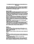
Ammeter – Voltmeter Method
This method consists of using both components to work out the resistance. The ammeter is connected in series and the voltmeter in parallel. A range of ammeter/voltmeter readings can be obtained by adjustments of the variable resistor. Below is an example of how the ammeter/voltmeter circuit should be built:
The process:
1. I will measure the resistance of 8 different lengths of Nichrome wire using an ammeter/voltmeter method.
2. For the first length, which will be 5cm, I will measure the current going through the wire and then I will measure the voltage across the 5cm of wire.
3. I will then find the resistance of the wire using V = IR, where I will have to divide the obtained voltage by the current reading to get the resistance.
4. I will repeat the above process for all the lengths of wire, ranging from 5cm to 40cm, at 5cm increments.
5. I plan to take three readings for each length of wire. Switching the supply on and off between each reading.
6. Because I will have three measurements for the resistance of each length of wire, I will find the average of these three readings.
7. I will record all the results in a table.
8. To guard against errors, I will repeat the whole process and compare the results.
List of apparatus:
- Ammeter
- Voltmeter
- Power pack
- Leads
- Resistance board
- Nichrome wire
- Crocodile clips
Ensuring it is a fair experiment:
To guarantee that the results are accurate and the test is fair, there are a few rules to abide by. Firstly the equipment should be checked to make certain that it works effectively, if working accurately the same set of equipment should be used throughout. Another factor is temperature, even though it is hard to make temperature stay constant, it is vital for it to remain unchanged to make sure it is a fair test. If the temperature increases so will the resistance, because of this, the power pack was switched off after each reading. Following the rules to make sure it is a fair test will also ensure reliable results but I will also take three repeats and find the mean so if one result is inaccurate; the others will average it out.
Safety:
Whilst carrying out the experiment it is essential to work in a safe environment. There are many precautions to be met; firstly it is important to work in an area away from water, as water is a good conductor. Secondly make sure that the circuit is properly connected before turning the power supply on and do not touch the apparatus, especially the tested wires until the power is switched off. Lastly do not switch on the power pack when there is no resistant wire and do not turn the power supply up too high, because this could lead to the wires melting.
Preliminary work
A preliminary test is used to figure out and solve any problems that exist in the experiment. The test allowed me to gather the most appropriate methods and equipment. I found out the following information for the test:
- I learned that using a resistance board is the most accurate technique of measuring lengths of wire.
- Nichrome wire has a high resistance, and so suitable for investigating the effect of a length of wire
- The power supply was set on two volts; this offered a small heating effect.
- I used an ammeter and voltmeter to receive the full range of current and voltage values; this will allow me to produce accurate resistance results.
- I used eight different lengths of wire; I learnt that this was a suitable range which will allow me to progress in the procedure.
- The thickness of the wire was the same throughout and was a suitable diameter, because it did not heat up easily. (I do not know the thickness of the wire, could you please note it! Thank you)
Set of results from preliminary test:
As well as being able to select the suitable equipment, this test showed difficullty in building a circuit. At first I found setting up a voltmeter/ ammeter and variable resistor into the circuit quite difficult, but whilst practicing in the preliminary test, I became fairly confident and built it accurately and promptly.
Method:
In my method I followed my plan, leaving it unchanged. (The plan can be found on page 4.) I repeated this process six times, to ensure accuracy of results and to solve any anomalous results. The measurement of the length of the wire was done in multiples of five, the resistance board included a 40cm wire, and therefore eight different lengths were experimented on, each going up by 5cm. After experimenting with the power supply on two volts, I trialed the test again, but this time setting the power supply on four volts.
Results
The table below shows my results whilst the power supply was set on two volts.
Results
The table below shows my results whilst the power supply was set on four volts.
Conclusion:
The results from the graph give a clear indication of how the resistance is proportional to the length. My line of best fit has a positive gradient as the length of the wire increases. This is because the charge carriers moving through the wire will have a longer distance to travel and encounter more collisions with more atoms as the length increases. Hence, as the length doubles, the number of obstructive atoms should double and the distance needed to travel doubles, therefore the resistance does double.
The results that I have obtained support my original prediction. By repeating the test I am confident of the accuracy of my results. The results from both tests were consistent. By keeping the diameter of the wire constant helped me to achieve this, as did the other fair test methods I employed. The line of best fit clearly shows that the results followed the expected pattern very well. The points are very close if not touching the line. This shows how the results were directly proportional through out, as the gradient remained the same. But at one point on the graph at two volts at twenty five centimeters length I feel I have an anomalous result. I put this down to the lack of control, in my test, of the temperatures of the wires.
If doing this test again I would like to develop a way to control the temperatures of the wires, giving me a better indication of the relationship. Also so that I have even greater accuracy I would use newer and more accurate ammeters and voltmeters over a wider range of lengths. I would also like to look into how the diameter affects the resistance.
It was important to have control over the factors that affect resistance; a key factor was the length of the wire; I controlled this by straightening out the wire before measuring to make sure there were not any kinks that would add to the length. One factor I felt I had lees control over was the potential difference applied, I was reliant on the power pack setting and in doing this investigation again I would look into setting greater control.