Cold extrusion is done at room temperature or near room temperature. The advantages of this over hot extrusion are the lack of oxidation, higher strength due to cold working, closer tolerances, good surface finish, and fast extrusion speeds if the material is subject to hot shortness. Materials that are commonly cold extruded include: lead, tin, aluminum, copper, zirconium, titanium, molybdenum, beryllium, vanadium, niobium, and steel. Examples of products produced by this process are: collapsible tubes, fire extinguisher cases, shock absorber cylinders, automotive pistons, and gear blanks.
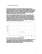
Figure 1 a plot of forces required by various extrusion processes.
Forward extrusion
Forward extrusion also known as direct extrusion, is the most common extrusion process. It works by placing the billet in a heavy walled container. The billet is pushed through the die by a ram. There is a reusable dummy block between the ram and the billet to keep them separated. The major disadvantage of this process is that the force required to extrude the billet is greater than that need in the backward extrusion process because of the frictional forces introduced by the need for the billet to travel the entire length of the container. Because of this the greatest force required is at the beginning of process and slowly decreases as the billet is used up. At the end of the billet the force greatly increases because the billet is thin and the material must flow radial to exit the die. The end of the billet, called the butt end, is not used for this reason.
Backward extrusion
In backward extrusion, also known as indirect extrusion, the billet and container move together while the die is stationary. The die is held in place by a "stem" which has to be longer than the container length. The maximum length of the extrusion is ultimately dictated by the column strength of the stem. Because the billet moves with the container the frictional forces are eliminated.
Advantages
There is a 25%-30% reduction in friction, which allows for extruding larger billets, increasing speed, and an increased ability to extrude smaller cross-sections.
Less heat is present as there is less friction leads to lower probability of cracks
The billet is used more uniformly so extrusion defects and coarse grained peripherals zones are less likely.
Disadvantages
Impurities and defects on the surface of the billet affect the surface of the extrusion. These defects ruin the piece if it needs to be anodized or the aesthetics are important.
This process isn't as versatile as direct extrusions because the cross-sectional area is limited by the maximum size of the stem.
Hydrostatic extrusion
In the hydrostatic extrusion process the billet is completely surrounded by a pressurized liquid, except where the billet contacts the die. This process can be done hot, warm, or cold, however the temperature is limited by the stability of the fluid used. The process must be carried out in a sealed cylinder to contain the hydrostatic medium. The fluid can be pressurized two ways:
Advantages
No friction between the container and the billet reduces force requirements.
There is an even flow of material.
No billet residue is left on the container walls.
Disadvantages
The billets must be prepared by tapering one end to match the die entry angle. This is needed to form a seal at the beginning of the cycle. Usually the entire billet needs to be machined to remove any surface defects.
Containing the fluid under high pressures can be difficult.
Metal Flow and Deformation
The below are observed during the extrusion process
- The velocity at the core of the metal is greater than at the outer layers.
- The outer layers are deformed to a greater degree than the core.
- The leading end of the extrude is almost undeformed.
-
The metal adjacent to the die does not flow easily, leading to the initiation of zones where little deformation occurs. These zones are called Dead-Metal-Zones.
Extrusion Defects
Defects in extruded parts usually fall under one of three main categories:
- Surface or internal cracking
- Sinking in
- Skin-inclusion defects.
Cracking is caused by secondary tensile stresses acting within a material having low plasticity. Cracks can occur in the form of a “fir-tree” or “central burst” when extruding materials such as steel and brittle aluminum alloys
Piping involves sinking of the material at the rear end of the billet. This defect is usually encountered toward the end of the extrusion stroke, especially when the initial billet length is short.
Skin inclusions depend on the degree of lubrication and the hardness of the surface layer of the initial stock material. With some materials, such as high copper alloys, the surface skin slides over the container wall and penetrates the billet.
Theory
An element of the deforming metal is subject to a state of stress involving triaxial compression, during an extrusion process. The high compressive stress state results in a considerable improvement in the plasticity of the deforming metal. Extrusion can be employed when working with metal having poor plasticity – as opposed to rolling or wire drawing where only ductile metals can be formed.
The formulas below can be used to provide an estimate for the extrusion pressure, P or force.
At times for simplicity extrusion force is calculated excluding the effect of friction and die angle
Homogeneous Deformation doesn’t take friction or die angle into account
Where Ao =
Al =
a is a constant to account for redundant work. blnR accounts for the amount of useful work where R is the extrusion ratio
a = 0.8; b = 1.5
Empirical expressions have been developed by research workers to give extrusion pressure as a function of the extrusion ratio and the mechanical properties of the metal.
Johnson – Empirical equation, which accounts for friction but does not take the die angle into account
For extrusion of a circular billet through a tapered die of included angle 2α in which the initial billet diameter is , the final diameter after extrusion is DA , and the coefficient of friction between the die and the billet is µ, and expression can be obtained for the extrusion pressure:
Modified equation to account for friction
Slab Analysis this equations accounts for both friction and the die angle into account though at
high die angles becomes impractical and inaccurate
Where R = ; ; -cone die angle
DB = Diameter of billet (25mm), DA = Diameter of Extrude (9.56mm),
Extrusion ratio R The yield stress , for the lead has been determined as 18N/mm2 from the compression test and the value of µ can be taken as 0.45.
Effective Extrusion ratio
Experimental Rig
Figure 2 Instron Press extrusion machine similar to that used in the lab
- Select die and place it in core of tool-set.
- Secure base plate invert and place in tool-set holder.
- Lubricate billet and place in tool base.
-
Select cross-hear movement speed at 2mm/min and chart 20mm/min.
- Bring cross head platen down until it almost touches the top of the extrusion ram using quick control mechanism.
- Rest load
- Reset Gauge
- Use fine tuning to make contact
- Repeat reset
- Then start extrusion at 1mm/min
- Apply constant cross head movement ensuring that the chart drive is on.
- Continue until a decrease in the extrusion load is noticed extruding a total of 9mm
- Remove die from tool set and repeat for each die.
Calculations
Below are example calculations
Homogeneous deformation
Johnson equation
P = 63.3MPa
Slab Analysis
Using 150’ angle for this example
Square die
Where
Hexagonal die
Graphs
Graph 1
Graph 2
Graph 3
Results
Results for theory are found using slab analysis formula above
Errors
Not putting the same amount of grease on each test
Billets have been recycled and may have underwent changes in the microstructure
Billets may not have been the exact same size
Die may have been worn leading to inaccuracies in the geometry
The assumption that the equipment is calibrated
Discussion
Section 1
From graph 1 180 degree die has the highest load this is most likely due to dead metal, causing redundant work to get rid of this build up of dead metal. The process with the lowest load takes place with a 90 degree die, this is as expected as 90 degrees die in theory would be the die angle we would expect the material to shear at, and friction and redundant work are also very low at 90 degrees in theory. The data on the graph above highlights the effect of redundant work and friction with the angles furthest from 90 degrees 180 and 60 being the two with the highest required load.
Section 2
Graph 2 shows the clear difference in required load for forward and backward extrusion, with the load required for forward being over 50kN and the load for backward being under 30kN.
This is as expected and is due to the billet not moving in backward extrusion leading to less friction.
Section 3
From graph 3 it is clear that the square die required the highest load to extrude the metal most likely caused by the square die having largest circumference therefore the highest friction. The circular and hexagonal dies appear to have much the same slope, with the circular die requiring slightly more load, this was not expected as in theory the circular die should require the least. I will account why this mite of happened in the errors section of the report.
The results above comparing the theoretical and the experimental values show that the experimental values found, though were in the general region were not what was expected from the theoretical values, these can be explained from the errors, expanded on in the errors section above.
Conclusion
That redundant work has a greater impact on load than friction
Backward extrusion definitely requires far less load than forward
That a 90 degree die angle requires the least force when using a circular die
That if redundant work and friction can be minimized, less loads is required for extrusion
That the slab analysis equation is an approximation and doesn’t take likely errors into account
That there were errors in this experiment
Reference
Ashby and Jones Engineering Materials Volume 1 third edition
Lab handout
Bauser, Martin; Sauer, Günther; Siegert, Klaus (2006), Extrusion