In the sketch diagram above, the centre line remains at its original length while the material above is compressed and the material below is stretched. This line is referred to as the neutral axis. Two important observations can be made from my knowledge: Firstly, the top and bottom portions need to resist larger forces than the central axis. Secondary, the top portion has to be strong in resisting compression force and the bottom strong in resisting tension force.
A beam bridge needs to be stiff. It needs to resist twisting and bending under load. So the material to make the beam is very important. Concrete or steel are the most popular materials for building bridges. Concrete is good at resisting compression force but poor in resisting tension force. In order to make the lower portion of a concrete beam strong enough, steel rods are added as reinforcement since steel is good at resisting tension force. This principle of physics is the origin for the invention of reinforced concrete which is often used in building beam bridges.
The Arch Bridge:
Arch bridges are one of the oldest types of bridges. They have semicircular structure with abutments on each end. This design is to allow the bridge naturally diverts the weight from the bridge deck to the abutments. They were originally built of stone or brick but these days are built of reinforced concrete or steel. This reason is the physical properties of concrete is much stronger in compression than both stone and brick.
The force of compression is pushed outward along the curve of the arch toward the abutments when the bridge is under load. The diagram below show how these compression forces dissipated step by step.
The tension in an arch is negligible. The tension on the underside of the arch is greatly reduced as the natural curve has dissipated the force outward. Therefore, an arch bridge can be built using only stones or concrete (which we know are not good for resisting tension).
The Cantilever Bridges:
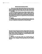
Cantilever bridges are a modified form of the beam bridge, with the support being placed not at the end, but somewhere in the middle of the span. They have a cantilever coming out from each side and a beam bridge in between them. A cantilever bridge (most common, with 3 span):
From the image it clear that the huge pillars take up the compression which are held up by the narrow top members. Attached to these are the complicated struts and cross bracing which withstand the forces causing buckling and twisting. The outer cantilevers have counterweights at the ends to maintain balance.
A Complete Three Span Cantilever Bridge
Cantilever bridge can be considered very strong. They are not as strong as a continuous beam bridge of the same length, but they are stronger than a comparable simple beam bridge. It is Because those spans (usually 3) will act as one structure.
The Suspension Bridges:
Unlike arch bridge, a suspension bridge supports its load by pure tension. Cables are strung across the river (or whatever the obstacle happens to be) and the deck is suspended from these cables. The cables are extended from one end of the bridge to the other. These cables rest on top of high towers and have to be securely anchored into the bank at either end of the bridge. The towers are important because they enable the main cables to be stretched out over long distances. Most of the weight or load of the bridge is transferred by the cables to the anchorage systems.
We now deal with the two main forces acting on their physical structure. The force of compression pushes down on the suspension bridge's deck, but because it is suspended, the cables transfer the compression to the towers, which dissipate the compression directly into the foundations. The tension forces are acting on the supporting cables between two anchorages. The cables are stretched under the weight of the bridge deck and the load placed on the bridge deck. The anchorages are also under tension in reaction to the cables, but since they, like the towers, are held firmly to the earth, the tension they experience is dissipated. To show these ideas carefully, sketched diagram below would be very helpful to show the physics involved.
There are mainly 2 types of suspension bridges. The normal suspension bridge which is recognized by the ‘M’ shape and the cable-stayed bridge which is recognized by the ‘A’ shape. They are recognized by these letters as the whole structure look like them.
The cables used for building are made of thousands of individual steel wires bound tightly together. Steel, which is very strong under tension, is an ideal material for cables; a single steel wire, only 0.1 inch thick, can support over half a ton without breaking. This material is used because it has a very high Young’s modulus, which is the measure of the stiffness of materials. The greater the value of the modulus the stiffer the material, and the less it stretches for a given force.
The Tsing Ma Bridge
It is easier for me to show how amazing these building technique is and the physics (forces, material…) by showing an example. As I am from Hong Kong, the Tsing Ma Bridge in Hong Kong is used for this example.
The Tsing Ma Bridge, which spans 1377m across the busy Ma Wan Channel, is the second longest bridge in the world after the Humber Bridge in Britain. However, it is the longest bridge that carries both motorway and railway in the world. It was designed to carry two three-lane carriageways on the upper deck and two railway tracks on the lower deck.
There are many components in the construction of the Tsing Ma Bridge. But I will be describing few major components briefly and cut them short.
For foundation and construction of the bridge towers; Both towers are 206m above sea level and founded on relatively shallow bedrock which are made by massive constructions. The towers are two-legged with trusses at intervals. The legs were constructed with high-strength concrete of 100 MPa strength which can handles the forces well. The pulling forces in the main suspension cables are taken up by large gravity anchorages located at both ends of the bridge. The total weight of concrete used in the two anchorages is about 300,000 tonnes.
A total of 70,000 galvanised wires of 5.38 mm diameter were placed and adjusted to form the 1.1 m diameter main cable. They can manage a ridiculous large amount of tension forces. A total of 96 modules, each 18 m long and about 480 tonnes in weight, were prepared. These deck modules were brought to the site by specially designed barges and raised into the deck position by a pair of strand jack gantries that could manoeuvre along the main cable.
There are also two sheltered single-lane carriageways on the lower deck for maintenance access and as backup for traffic during typhoons when wind speed is still within acceptable limits. The construction cost of Tsing Ma bridge is $7.14 billion and the actual completion time was 57 months.
Resonance & Torsion:
Resonance and torsion are two of the main factors needed to be considered carefully when a bridge is being built. The definition of resonance; ‘In general, whenever a system capable of oscillation is acted on by a periodic series of impulse having a frequency equal to or nearly equal to one of the natural frequencies of oscillation of the system, the system is set into oscillation with a relatively large amplitude.’ Torsion is a rotational or twisting force; it has been effectively eliminated in all but large suspension bridges. It is because they are suspended, are more susceptible to torsion, especially in high winds. They are very important that can cause a bridge to collapse- e.g Tacoma Barrows bridge.
Tacoma Barrows Bridge:
The dramatic Tacoma Narrow bridge disaster happened in 1940. The disaster happened because simply the wind was providing an external periodic frequency that matched the natural structural frequency, and produced a fluctuating resultant force in resonance with a natural frequency of the structure. Causing an unstable oscillation occurred on the deck and tends to grow more gradually in amplitude and increase torsion force for the whole structure. Finally the oscillation and torsion forces has exceeded the limit that the bridge material can handle, so the bridge collapsed.
The major weakness in the Tacoma Narrows Bridge was its flexibility, both vertically and in torsion. One reason for this was that the ratio between the depth of the girders to the span of the bridge was very large. Another reason was the high ratio between the width and the span of the bridge.
Nowadays, engineers need calculate the frequency of external force (e.g wind, load) and the natural frequency of building material carefully before a bridge is built. It will be very danger if both frequencies are similar. Wind-tunnel test is also used, to avoid this disaster happen again.
Thermal expansion:
All materials undergo expansion when temperature rises, and contraction when temperature lowers. The thermal expansion coefficient indicates the amount of expansion in a given material corresponding to a unit temperature change. The thermal expansion coefficient is a very basic physical property which is very important to be considered when choosing building materials. Materials with low coefficient of expansion are more likely to be chosen with bridge building construction as they have lesser extensions comparing to others. Calculations are needed for choosing building materials, using equation (coefficient of expansion * temperature change * original length = extensions).
Each Particle inside the building material has an average energy of random thermal agitation of the order of magnitude kT, (k is the Boltzmann constant). So the energy of particles increase as the temperature. The energy will come to some stage that is strong enough to break the bond between particles inside the building material. So as the particles vibrate vigorously, they have increase the limited space inside the material and expand it outward.
There will be problems if this factor is not being considered seriously. Imagine what happen if large changes of temperature and the bridge deck is fixed rigidly at both ends. Then great compression forces will be developed when the deck expands and tension forces will be developed when the deck contracts. At fixed ends, there will be massive forces push directly to the joints at both ends when the deck is greatly expanded. The joints will break if the forces has exceeded the limit that they can handle. For the same idea, there will be massive forces pull from the joints at both ends as the deck greatly contract.
One suitable method to solve these problem is to use movable joints at one end rather than both joints are in fixed positions. Therefore the bridge deck can contract or expand freely, causing no extra compression or tension forces which may causes damages.
Conclusion:
From my report, many physics concepts are covered, I have explained how they relate to the design of bridges and how the physics ideas work in bridges construction. Also real life examples are also be included, in order to show how the physics really involved in the bridges which have already been built. Case studies help me to understand the physics concept in a deeper level.
From the analysis and comparison of different types of bridges. It has been shown that compression and tension forces are the main characters acting in bridges. Different types of bridges handle those forces differently. So deciding what type of bridge to build depends on the landscape and situation, e.g. Suspension bridge is more likely to be adopted if we need to span over a very wide river. Materials also need to be chosen to be strong enough to handle those forces for building bridges. I have realized that concrete and steel are the most common materials used for building bridges.
There are also many other physical concepts that need to be considered in bridge construction and there will be failure if they are ignored. For instance, I have researched into the Tacoma Barrows Bridge case to understand more how certain physics idea (especially resonance) work on bridge structure. Thermal expansion is another physics idea that acts as an important part in bridges. Engineers these days cannot ignore those factors, if they do not want failure to happen.
Through my research and writing of this essay, I have gained much insight into the relation between physics and engineering. This will help me a lot in my future study in Civil Engineering in the university. I find bridges construction is the most interesting topic in Civil Engineering so far.
Bibliography:
1) ‘Design & construction of bridges’ by Walter Podolny
Published by ‘Trafalgar Square’, April 1993
2) ‘Bridges’ by Judith Dupre
Published by ‘Black dog & Leventhal Pub’, Spetember 1997
3) ‘Bridgescape —The art of designing bridges’ by Frederick Gottemoeller
Published by ‘John Wiley & Sons’, April 1998
4) ‘What is a bridge?’ by Spiro N.Pollalis
Published by ‘MIT Press’, 9 September 2002
5) ‘15 Most Outstanding projects in Hong Kong’ by Raymond Wong Wai Man
Published jointly by the editorial teams of Building Journal and Construction & Contract News
6) Advancing Physics AS text book
7) Advancing Physics A2 text book
8) bridge resonance
9) Cantilever bridges
Additional information:
For the section of thermal expansion, I have asked my dad for help. My dad had explained a few concepts through a conversation in phone, I then dropped down some notes and write the whole page by myself.
Also, an email from my dad has helped me for a little that teach me the technique to write my conclusion. The email is shown in the next page.