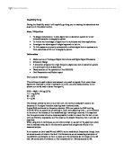
Diagram including (Input, Multiplier, ac Amp, PSD LPF and Oscillator)
Also in this Feasibility study we will want to look at the Dynamic Reserve (DR)
Dynamic Reserve is the amount of reserve that is available in order to preserve the system during a frequency disturbance. Therefore, the amount of Dynamic Reserve should be enough to allow the system to survive the loss of the largest energy contingency.
That is the ratio of the largest noise signal to signal that the lock in can tolerate without overloading. Once the project is undertaken we will then have to match V output to V range as closely as possible. The DR is measured in dB and a Dr5 of 60dB would indicate noise=1000signal (at full scale). In general the lowest DR, which does not cause overload, should be used.
Computer Interface
A computer interface would allow data from the lock-in to be connected directly to the computer. Due to complex nature of the data we are collecting in this experiment it would be useful to have this facility. When I look at other devices currently available I will consider this, it might be one of the main advantages of having a commercially available system modified for this application. If I follow the route of building our own system a computer interface would seen an unrealistic proposal due to its complexity. Though there may be the possibility of using a fast digitisation card, further research will be required in to this area.
Phase Sensitive Detection
At the heart of any lock in amplifier is phase sensitive detector (PSD). The detector multiplies the signal and the reference together.
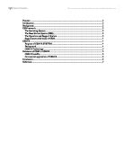
Graph (Signal in - Reference - Demodulator output)
The output is a sinusoidal at twice the reference frequency. The mean level of the resulting signal will be positive and not zero. See above graph.
If the signal and reference are not in phase then it can be shown that the mean level of the product of the signal and reference will be proportional to the product of the signal and reference frequency amplitudes. Furthermore it will also be related to the phase angle between the signal and reference. As the ideal situation is that the signal and reference are in phase we have the capability to carry out ´phase shift´ of the reference, to allow them to be in phase.
Following this we can find the mean level (DC component) using a low-pass filter to remover the 2wt component and measure using DC voltmeter. The above is based on technical mathematical derivation, which I shall not go in to at this stage. #
There are two different types of switching that can be used. Above is a multiplier type, which is preferred for this type of high speed use. I will now undertake a full literature search on phase sensitive detection.
Why Digital?
In the last model of near infrared absorption tomography system an analogue approach to lock-in detection was used. In the next page I will seek to explain why it is not only feasible but also preferable to use a digital lock-in technique.
Such devices are classed as digital once there phase sensitive detection is implemented in digital circuit form. (Digital not to be confused with digital electronics for control and output etc)
The advantages of digital lock-in are both far reaching and wide ranging. They are known to include.
1. Improved flexibility, thus allowing for the tomography systems specification to change without rendering the lock-in system useless.
2. Better price performance ratios. Reduced manufacturing and test costs along side better performance give the above result.
3.Use of crystal-stabilized internal oscillator give greater stability over increased temperature and time ranges, from which there are retrospective improvements.
4.Improved output stability. Unlike analogue units no DC coupled output amplifier stages are used and therefore less prone to drift over temperature and time.
5. Small or near zero lock acquisition time ideal for swept frequency measurements.
Dual Reference / Signal Mode
As mentioned in the project specification the device handles dual signals. Therefore two reference inputs are equal. This allows that instrument to make measurements at two different reference frequencies. Previously this have required a pair of lock in amplifiers (when implemented in a digital manor) in order that we achieve dual reference one of the references must be external. Furthermore the signal may need to be summed prior to measurement or use the devices differential input mode.
Current Products
Following investigation in to the availability of Digital Lock-in amplifiers I have found that there is very few with dual reference mode which is central for the application.
PerkinElmer instruments offer a range of amplifiers which could be used for our application, they are the 7200 range of digital lock-in amplifiers.
The 7200 series can be used in either Differential voltage mode or current input mode. In current input mode you can either select 10^6V/A conversion to voltage for high bandwidth or 10^8V/A conversion for low noise. If necessary a separate dedicated current preamplifier can be used.
Should I be able to keep the AC gain at a low (but sensible) level the real signal will only occupy a few bits of the ACD´s dynamic range. As Previously the DR (Dynamic Reserve) gives an indication of the devices ability to deal with stronger interface signals without overload. The 7260 (cost £2650 ex demo) has a Dynamic reserve over 100 dB, computer interfaces. 2 nV sensitivity, 1 mHz to 250 kHz operation
The 7200 series also has an effectives anti-aliasing filter which removes unwanted frequencies (those which would cause spurious output from the ACD). The anti aliasing filter achieves this by restricting the bandwidth reaching the ACD. If there were no problems with noise then it would be possible to by-pass this filter, this though is not the case for our problem.
In order that you can monitor the effects of the signal filters and amplifiers a buffered output of the signal just prior to the ADC is available at the rear or the device.
Analogue to Digital converter
As mentioned in the project specification due to the Niquist sampling theorem the sampling rate would need to be twice the bandwidth of the anti-aliasing filter, on our circuit. Due to the dual modulation frequency, this will, in our case be high. Therefore we will require a high sampling rate.
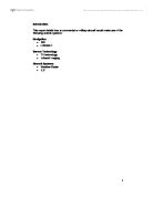
(Diagram of the 7200 series block diagram)
On the previous page is a block diagram of the 7200 series, hopefully this will aid understanding of the circuit components that I have explained in this piece.
Reference Channel
The main reason for having a reference channel is to ensure that the demodulator (DSP) is provided with the "phase values" at the same time as the ADC. The values give an instantiations phase angle for the reference frequency.
This will allow the second digital signal processor (as a phase locked loop) to measure the period of the signal and generate further phase angle values.
One of the main differences between digital lock-in and analogue is that the reference channel is not dependant on a phase locked loop. Therefore there is a decrease in the phase noise, making it extremely low. This is due to the phase lock accruing instantaneously.
Phase Shifter
Once again the signal processor is used to implement a phase shift by adding or subtracting a reference phase. The 7200 have a resolution of 10millidegrees. The lock-in amplifier provides a TTL (transistor transistor logic) signal of the reference frequency therefore allowing us, the users, to check the reference channel.
Second Stage Output Filters
Under normal circumstances digital lock-in uses digital infinite impulse response filters though the 7200 series uses finite impulse response low-pass filters off 6, 12 and 18 dB/Octave Role off.
Microprocessor Control
The digital lock-in also incorporates a microprocessor, this deals with a number of the signal functions (processes) and allows for computer interface.
Dual Reference / Signal Mode
The main reason why the PerkinElmer 7200 series are the only products available for this project is its dual reference mode, as mentioned earlier in the section). We require that signals are decoded form the two frequencies of modulation after being received by the 550-um-diam fiber and detected by the InGaAs photodiode.
Lock-in using the 68HC11 Micro controller
With a 68HC11 and IBM PC as a host system it is possible to develop a digital lock-in system. Through the use of a signal generator and data acquisition for digital quadrature the lock-in is implemented. The “Babes-Bolyai” University in Romania developed a digital lock-in system that operates over a frequency range of 1 –1000Hz, which is very significantly below that which is required for our system. It did though have a typical error of less than .5% (20 log (100/.5 = 46dB). The main source of noise was from the low resolution of the ADC subsystem. Very good flexibility and stability was reported. Following my investigation I have found that unfortunately it will not be possible to use a microprocessor-based approach as a high enough sampling rate cannot be achieved. This is one of the major findings of this feasibility study. The obvious alternative is to use a DSP processor with fast isolation ADCs.
Other Devices Continued
While researching other devices I found information from the University of Texas regarding PC-Based Digital Lock-in detection. I have been able to discount this potential solution to our problem as I found that a PC based approach cannot provide a high enough sampling rate. PC based approach is only useful for slowly varying small signals in the presence of noise, for example assessing the onset of superconductivity in a material over time.
I have also found sketchy information regarding the NF Corporations LI5640 and 5630 though the data available over the Internet was not of a high enough standard and depth. I have ordered the catalogue for said device.
Conclusion
The Perking Elmer 7200 series shows promise in its ability to be applied to our problem. I will attempt to borrow or loan one of these devices for further analysis. Within this feasibility study I have also come across anecdotal evidence that a digital approach to lock-in detection would not normally be used at the frequencies that are required in the project that I am undertaking, I will over the forcible future be researching this. During the study I have been able to discount the PC based approach and have found that there will not be the possibility of a microprocessor approach, due to not being able to achieve a high enough sampling rate.
References:
PerkinElmer Technical Note 1000
Physica B vol.208-209
PerkinElmer Technical Note 1003
Physics 344 uiuc
NF Corporation Products 5640
PC-Based Digital Lock-In Detection of small signals University of Texas
Notes MSc Lectures ESI Dr w. Yang
Notes Electronic Systems – Instrumentation Systems Prof. Hugh McCann