I0=Moment of inertia of the platform.
M0=Mass of platform
I=Moment of inertia of body
M=Mass of body
g=Acceleration due to gravity
Results
Discussion
In this experiment two different sets of readings where gathered and recorded. Both the bar and the rod where tested by the trifilar method. However the rod was placed under one more test, the knife edge, results for these experiments can be seen on table one.
We also noticed that there was a great difference in our results, that is the ones obtained experimentally differed from the theoretical ones by about 0.015.For instance the result that was gotten by the trifilar method for the rod was not similar to the knife edge method, in addition theoretical values where lower that experimental values.
The discrepancy in the results could be in the swinging method, as the person holding the platform in the trifilar method may have given it some extra moment by a push as it can be the case in the knife edge experiment.
Further more, the connecting rod was tested two ways when in knife edge, hanging from the smaller joint and hanging by the larger joint. On both these cases the measurement for L changed as the distance from the hanging point to the centre of mass also changed.
The rod had inertia of 0.064 in the trifilar method, but on the hanging method the value for inertia came down to 0.042, this difference of 0.022 is our error. This discrepancy could be due to a miscount, problems with the timing, extra moment, human error etc.
Conclusion
During this experiment we discovered that there is a big difference in theory and practice. And not only that but some methods can give discrepancies between themselves.
It was also worth noticing the values of inertia these moving parts had, as it gives the designer and the manufacturer a good idea of the performance of the part. In this case a connecting rod was considered but another example would be a helicopter blade, or rotor blade. The blades of the helicopter are under constant movement once the engine is on and good idea on the inertia can aid with the performance of the helicopter as well as make the machine more efficient.
Appendix
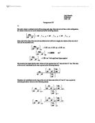
When the platform is rotated
rθ = Lφ, or φ = rθ / L
If tension in each wire is T, then its vertical component is T⋅cosθ.
As angle φ is small
3T = Mo⋅g or T = Mo⋅g / 3
The horizontal component T⋅sinφ is tangential to ‘r’ and if α is the angular acceleration of the platform, from equation ∑MG = IG⋅α (∑MG, moment of the rotation axis through the centre of mass G)
-3r⋅T⋅sinφ = Io⋅α
As angle φ is small,
-3r⋅T⋅φ = Io⋅α
-3r⋅(Mo⋅g / 3)⋅(rθ / L) = Io⋅α
Finally,
-(g⋅r2⋅Mo / L)⋅θ = Io⋅α
With the body on the platform, the total mass is Mo + M and moment of inertia is Io + I, so the equation is
-[g⋅r2⋅(Mo + M) / L]⋅θ = (Io + I)⋅α
As T n = 2π / ω n
T n = 2π⋅√[L⋅(Io + I) / g⋅r2⋅(Mo + M)
From equation ∑Mo = Io⋅α
-M⋅g⋅⋅θ = I1⋅α
Where I1 is the moment of inertia about the fixed axis through the point of suspension parallel with the axis through the centre of mass G.
ωn2 = M⋅g⋅/ I1
T n = 2π⋅√(M⋅g⋅/ I1)
I1 = (T2 / 4π2)⋅ M⋅g⋅
from the parallel theorem IY1Y1 = IYY + M⋅(/ 2)2
I1 = IG + M2
For the theoretical work
I2 = (M / 12)⋅(2 + W2)
Where I2 is the moment of inertia of a rectangular bar about the axis YY through the centre of mass G