Scalability: Wireless LAN systems can be configured in a variety of topologies to meet the needs of specific applications and installations. Configurations are easily changed and range from peer-to-peer networks suitable for a small number of users to full infrastructure networks of thousands of users that enable roaming over a wide area.
Wireless LAN Technologies
There are several wireless LAN specifications and standards available to choose from when deploying wireless LAN products or integrating wireless LAN solutions into corporate information systems. The following sections provide a brief overview of these specifications and standards. The emphasis of this report is on the IEEE 802.11b wireless LAN, due to the fact that 802.11 is expected to continue being the preferred standard for supporting wireless LAN applications. Other technologies, such as HiperLAN, HomeRF and Bluetooth may become stronger competitors to 802.11 in the future (Cisco 2001).
IEEE 802.11
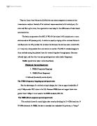
In June 1997, the Institute of Electrical and Electronics Engineers (IEEE) finalised the initial standard for Wireless LANs: IEEE 802.11(Intel 2002).
This standard specifies a 2.4Ghz operating frequency with data rates of 1Mbps and 2Mbps. The initial 802.11 standard defines two forms of spread spectrum modulation: frequency hopping spread spectrum (802.11 FHSS) and direct sequence spread spectrum (802.11 DSSS) (Kohlhepp 2000).
Spread spectrum is a modulation technique developed in the 1940s that spreads a transmission signal over a broad band of radio frequencies. This technique is ideal for data communications due to the fact that it is less susceptible to radio noise and creates little interference. Both FHSS and DSSS technologies are described in more details in section 5.1.1 (FHSS vs. DSSS) later in the report (Foster 2001) and (Molta 2002).
In the late 1999, the IEEE published two supplements to the 802.11 standard: 802.11a and 802.11b.
IEEE 802.11b is a data rate extension of the initial 802.11 DSSS, providing operation in the 2.4 GHz band up to 11Mbps. Most wireless LANs implemented today use the 802.11b version of the standard (Planet 2001), (Proxim 2001) and (Collins 2000).
802.11 FHSS is limited to a 2-Mbps data transfer rate and is recommended for only very specific applications such as certain types of watercraft. FHSS does not support data rates greater than 2 Mbps (Proxim 2001) and (Geier 2001).
The implication of using different types of spread spectrum techniques is that 802.11b systems will interoperate with 1 Mbps and 2 Mbps 802.11 DSSS systems, but will not work with 1 Mbps and 2 Mbps 802.11 FHSS systems (Dornan 2000).
The 802.11a standard defines operation at up to 54Mbps using Orthogonal Frequency Division Multiplexing (OFDM) modulation in the 5Ghz frequency band. The 802.11a standard has a wide variety of high-speed data rates available: 6, 9, 12, 18, 24, 36, 48 and 54Mbps. Products implementing the 802.11a standard should begin appearing on the market in beginning of 2002 (McCallough 2001), (Proxim 2001) and (Geier 2001).
Figure 1 illustrates the development of the 802.11 standard.
HiperLAN
HiperLAN began in Europe as specification (EN 300 652) ratified in 1996 by the European Telecommunications Standards Institute (ETSI) Broadband Radio Access Network (BRAN) organisation. HiperLAN/1, the current version, operates in the 5Ghz radio band at up to 24Mbps. Similar to Ethernet, HiperLAN/1 shares access to the wireless LAN among end user devices via a connectionless protocol. HiperLAN/1 also provides Quality of Service (QoS) support for various needs of data, video, voice and images (Young 2001) and (Rogers 2001).
ETSI is currently developing HiperLAN/2 under an organisation celled the HiperLAN/2 Global Forum (H2GF). HiperLAN/2 will operate in the 5GHz band at up to 54Mbps using a connection oriented protocol for sharing access among end user devices. HiperLAN/2 will include QoS support and be capable of carrying Ethernet frames, ATM cells and IP packets (Geier 2001).
HomeRF SWAP
In March 1998, the HomeRF Working Group (HFRWG) announced its existence and set out to provide an open industry specification, Shared Wireless Access Protocol (SWAP), for wireless digital communication between PCs and consumer electronic devices within the home. The SWAP specification defines a common wireless interface supporting voice and data at 1Mbps and 2Mbps data rates using frequency hopping spread spectrum modulation in the 2.4GHz frequency band. HRFWG is currently developing a 10Mbps version of SWAP based on recent Federal Communications Commission (FCC) approval for wider bandwidth for frequency hoping systems (Rogers 2001) and (Sayre 2001).
Bluetooth
Bluetooth is a specification published by the Bluetooth Special Interest Group (SIG), with some big promoters including 3COM, Ericsson, IBM, Intel, Microsoft, Motorola, Nokia and Toshiba. Bluetooth is not a wireless LAN. Instead, it is a wireless personal area network (PAN), which is a subset of a wireless LAN. Bluetooth operates at 1Mbps, with relatively low power over short ranges using frequency hopping spread spectrum in the 2.4GHz frequency band (Miller 2001).
Spread Spectrum Technology
The obvious way to begin the design of a wireless LAN architecture would be to fix a signal at a certain frequency and use that as the "wire" of communication. As mentioned earlier in Chapter 4.1 (IEEE 802.11) most wireless LAN systems use spread spectrum technology, which is a wideband radio frequency technique developed by the military. Spread spectrum, as the name implies, uses multiple frequencies in the band to increase the immunity to noise at any specific frequency (Phifer 2001).
Understanding Spread Spectrum
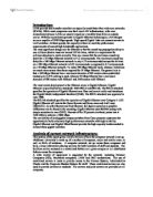
Modulation is a process in which the radio transceiver prepares the digital signal within the network interface card (NIC) for transmission over the airwaves. Spread spectrum “spreads” the signal’s power over a wider band of frequencies, sacrificing bandwidth in order to gain signal-to-noise performance. Figure 2 on next page illustrates the concept. This contradicts the desire to conserve frequency bandwidth, but the spreading process makes the data signal much less susceptible to electrical noise than conventional radio modulation techniques. Other transmission and electrical noise, typically narrow in bandwidth, will interfere with only a small portion of the spread spectrum signal, resulting in much less interference and fewer errors when the receiver demodulates the signal (Nortel 2001) and (Molta 2002).
A narrowband radio system transmits and receives user information on a specific radio frequency. Narrowband radio keeps the radio signal frequency as narrow as possible just to pass the information. Undesirable cross talk between communications channels is avoided by carefully coordinating different users on different channel frequencies (Molta 2000).
Spread-spectrum is designed to trade off bandwidth efficiency for reliability, integrity, and security. In other words, more bandwidth is consumed than in the case of narrowband transmission, but the trade-off produces a signal that is, in effect, louder and thus easier to detect, provided that the receiver knows the parameters of the spread-spectrum signal being broadcast. If a receiver is not tuned to the right frequency, a spread-spectrum signal looks like background noise (Intel 2002) and (Geier 2001).
As mentioned earlier in section 3.3.1 (IEEE 802.11) there are two types of spread spectrum radio currently being used for the IEEE 802.11 Wireless LAN standard transmissions, FHSS and DSSS. Succeeding section compares these two technologies.
FHSS vs. DSSS
Some Wireless LAN network products, such as Raytheon's RaylinkTM products, use the frequency hopping method of spreading their signals. It modulates the data signal with a carrier signal that hops from frequency to frequency as a function of time over a wide band of frequencies. An IEEE 802.11 frequency hopping radio, for example, will hop the carrier frequency over the 2.4GHz frequency band between 2.4GHz and 2.483GHz.
A hopping code determines the frequencies the radio will transmit and in which order. To receive the signal properly, the receiver must be set to the same hopping code and listen to the incoming signal at the right time and correct frequency (Rogers 2001) and (Sayre 2001).
In DSSS, the stream of information to be transmitted is divided into small pieces, each of which is allocated across to a frequency channel across the spectrum. A data signal at the point of transmission is combined with a higher data-rate bit sequence, which many refer to as a chipping code or also known as a processing gain that divides the data according to a spreading ratio. The redundant chipping code helps the signal resist interference and also enables the original data to be recovered if data bits are damaged during transmission (Proxim 2001) and (Geier 2001).
FHSS and DSSS techniques are both used in IEEE 802.11 wireless LAN systems due to the fact that they are designed to be resistant to noise, interference, jamming, and unauthorized detection. DSSS systems are much harder to build with high user density limitations, but it provides a slight data speed and range advantages over FHSS. DSSS systems are ideal for data warehouse applications where the data user density is small and range is a critical need (Proxim 2001) and (Geier 2001).
As mentioned earlier FHSS systems may have data speed limitations and be shorter in range, but they are easier to build and therefore cost less. FHSS are very good at avoiding narrow band interference and unauthorized user access due to their frequency hopping nature. FHSS systems are good for high user density areas such as healthcare applications (Techguide 2000) and (Lahti 2000).
The IEEE 802.11 Wireless Standard
In May 1991, a group led by Victor Hayes submitted a Project Authorisation Request (PAR) to IEEE to initiate the 802.11 working group. Hayes became chairman of the working group and led the standards effort to its completion in June 1997.
In September 1999 they ratified the 802.11b “High Rate” amendment to the standard, which added two higher speeds (5.5 and 11 Mbps) to 802.11 (Intel 2002).
Benefits of the 802.11 Standard
The goal of 802.11 is to provide a standard set of operational rules so that Wireless LAN products from different manufacturers interoperate in the way that Ethernet equipment does today.
In the past, few Wireless LAN vendors offered products that functioned with products from other companies. If a customer deployed one brand of wireless product, it was not likely to work with another vendor’s product. The 802.11 standard is a key development that results in interoperability among wireless LAN vendors. As a result of the standard, companies that supply components for wireless LAN products may now develop components compliant with the standard, which helps lower costs. Customers may also have confidence that their investment in Wireless LAN solutions is protected through multiple vendor compatibility (Proxim 2001), (Intel 2002) and (Foster 2001).
IEEE 802.11 Topology
802.11 defines two pieces of equipment, a wireless station, which is usually a PC equipped with a wireless network interface card (NIC), and an access point (AP), which acts as a bridge between the wireless and wired networks (Proxim 2001).
The 802.11 standard supports the following two topologies:
- Independent Basic Service Set (IBSS) networks
- Extended Service Set (ESS) networks
These networks use a basic building block the 802.11 standard refers to as a BSS, providing a coverage area whereby stations of the BSS remain fully connected. A station is free to move within the BSS, but it can no longer communicate directly with other stations if it leaves the BSS (Cisco 2001).
An IBSS is a standalone BSS that has no backbone infrastructure and consists of at least two wireless stations as illustrated in Figure 3 (Cisco 2001).
This type of network is often referred to as an ad hoc network because it can be constructed quickly without the need of an access point.
The ad hoc wireless network will satisfy most needs of users occupying a smaller area where a wireless infrastructure does not exist or is not required for services, such as a hotel room, convention centre, or airport.
For requirements exceeding the range limitations of an independent BSS, 802.11 defines an Extended Service Set (ESS) LAN, as illustrated in Figure 4 (Cisco 2001).
The 802.11 standard defines the distributed system as an element that interconnects BSSs within the ESS via access points.
Since most corporate Wireless LANs require access to the wired LAN for services such as, file servers, printers, Internet links they will operate the ESS mode (Foster 2001).
Roaming
When 802.11 is operating in ESS LAN, two or more access points are necessary to cover the required area. When using multiple access points, each access point’s wireless area should overlap its neighbour’s area, providing a seamless area where mobile users can move around without losing connection to the network. This is illustrated on next page in Figure 5. When moving around, there will be a handover from one access point to the next. This process is called roaming (Geier 2002a).
The client is responsible for choosing the most appropriate access point based on the signal strength, network utilization and other factors. When a station determines the existing signal is poor, it begins scanning for another access point. This can be done by passively listening or by actively probing each channel and waiting for a response.
Once information has been received, the station selects the most appropriate signal and sends an association request to the new access point. If the new access point sends an association response, the client has successfully roamed to a new access point (Geier 2002a) and (Intel 2002).
IEEE 802.11 Logical Architecture
Like all IEEE 802 standards, the 802.11 standards focus on the bottom two levels of the Open Systems Interconnection (OSI) model, the physical layer and data link layer. This is illustrated in Figure 6. Any LAN application, network operating system, or protocol, including TCP/IP and Novell NetWare, will run on an 802.11 compliant Wireless LAN as easily as they run over Ethernet (Conover 2000) and (Nortel 2001).
The basic architecture, features, and services of 802.11b are defined by the original 802.11 standard. The 802.11b specification affects only the physical layer, adding higher data rates and more robust connectivity (Conover 2000).
As illustrated in previous page in Figure 6, the logical architecture of the 802.11 standard that applies to each station consists of a single media access control (MAC) protocol layer and one of multiple physical (PHY) transport protocol layer (Conover 2000).
IEEE 802.11 Physical Layers
The Physical layer provides for the transmission of bits through a communication channel by defining electrical, mechanical and procedural specifications.
As illustrated in Figure 6 on previous page the 802.11 standard specifies several Physical layers. The initial standard approved in 1997 included frequency hopping and direct sequence spread spectrum, delivering data rates of 1 and 2 Mbps in the 2.4GHz band. The 2.4 GHz band was chosen because it is available for unlicensed operation worldwide and because it is possible to build low cost, low power radios in this frequency range that operate at LAN speeds (Conover 2000) and (Nortel 2001).
This initial release also defined an Infra-Red Physical layer operating at 1 and 2Mbps via passive ceiling reflection. The current 802.11 standard, released in December 1999, added an 11Mbps, high-rate version direct sequence standard commonly referred to as IEEE 802.11b (Conover 2000).
In addition, the current standard defines a Physical layer using OFDM to deliver data rates of up to 54Mbps in the 5GHz frequency band (802.11a) (Foster 2001).
IEEE 802.11 Data Link Layer (LLC and MAC)
The data link layer within 802.11 consists of two sub-layers: Logical Link Control (LLC) and Media Access Control (MAC) (Techguide 2001).
Logical Link Control (LLC)
As illustrated in Figure 6, the 802.11 uses the same 802.2 LLC and 48-bit addressing as other 802 LANs, allowing for very simple bridging from wireless to IEEE wired networks. Basically, the LLC provides addressing and data link control and it is independent of the topology, transmission medium and medium access control techniques chosen (Techguide 2001), (Conover 2000) and (Nortel 2001).
Media Access Control (MAC)
The MAC layer in 802.11 specifies the “rules of access” to a shared medium and is composed of several functional blocks (Geier 2001) and (Conover 2000).
Basically, the MAC layer provides three primary operations:
- Accessing the wireless medium
Before transmitting a frame, the MAC coordination must first gain access to the network using Carrier Sense Multiple Access with Collision Detection (CSMA/CD).
Once a station is turned on, it needs to first determine whether another station or access point is present to join before authenticating and associating with an applicable station or access point.
- Providing authentication and privacy
Because of the open broadcast nature of Wireless LANs, appropriate level of security is essential, such as shared key authentication.
The above mentioned operations within the MAC are independent of data rates or physical characteristics. The succeeding sections will describe these operations in more details.
Accessing The Wireless Medium
The 802.11 MAC is very similar in concept to 802.3, in that it is designed to support multiple users on a shared medium by having the sender sense the medium before accessing it. For 802.3 Ethernet LANs, the Carrier Sense Multiple Access with Collision Detection (CSMA/CD) protocol regulates how Ethernet stations establish access to the wire and how they detect and handle collisions that occur when two or more devices try to simultaneously communicate over the LAN (Geier 2001) and (Conover 2000).
In an 802.11 Wireless LAN, collision detection is not possible due to what is known as the “near/far” problem: to detect a collision, a station must be able to transmit and listen at the same time, but in radio systems the transmission drowns out the ability of the station to “hear” a collision (Conover 2000).
To account for this difference, 802.11 uses a slightly modified protocol known as Carrier Sense Multiple Access with Collision Avoidance (CSMA/CA) or the Distributed Coordination Function (DCF). CSMA/CA attempts to avoid collisions by using explicit packet acknowledgment (ACK), which means an ACK packet is sent by the receiving station to confirm that the data packet arrived intact (Rogers 2001) and (Geier 2001).
CSMA/CA
The CSMA/CA protocol allows for options that can minimize collisions by using request to send (RTS), clear to send (CTS), data and acknowledge (ACK) transmission frames, in a sequential fashion (Conover 2000). This concept is illustrated in Figure 7.
Communication is established when one of the wireless nodes sends a short-message RTS frame. The RTS frame includes the destination and the length of the message. The message duration is known as the network allocation vector (NAV). The NAV alerts all other users of the medium to back off for the duration of the transmission. The receiving station issues a CTS frame, which echoes the sender’s address and the NAV. If the CTS frame is not received, it is assumed that a collision occurred and the RTS process starts over. After the data frame is received, an ACK frame is sent back verifying a successful data transmission (Geier 2001) and (Conover 2000).
Basically the CSMA/CA works by a “listen before talk” scheme (Conover 2000).
A station wishing to transmit must first “listen” to the radio channel to determine if another station is transmitting. If the medium is not busy, the transmission may proceed. The CSMA/CA scheme implements a minimum time gap between frames from a given user. Once a frame has been sent from a given transmitting station, that station must wait until the time gap is completed to transmit again. Once the time has passed, the station selects a random amount of time (called a back-off interval) to wait before “listening” again to verify a clear channel on which to transmit (Geier 2001) and (Conover 2000).
If the channel is still busy, another back-off interval is selected that is less than the first. This process is repeated until the waiting time approaches zero and the station is allowed to transmit.
The Hidden Node Problem
A common limitation with the MAC layer within Wireless LAN systems is the “hidden node” problem. It occurs when two stations on opposite sides of an access point can both “hear” activity from an access point, but not from each other, usually due to distance or an obstruction (Conover 2000). This is illustrated below in Figure 8.
In order to address this problem, an RTS/CTS is specified as an optional feature of the IEEE 802.11 standard. When this feature is in use, a sending station transmits an RTS and waits for the access point to reply with a CTS.
Since all stations in the network can hear the access point, the CTS causes them to delay any intended transmissions, allowing the sending station to transmit and receive a packet acknowledgment without any chance of collision.
Since RTS/CTS adds additional overhead to the network by temporarily reserving the medium, it is typically used only on the largest-sized packets, for which retransmission would be expensive from a bandwidth standpoint (Geier 2001) and (Conover 2000).
Joining a Network
Once a station is turned on, it needs to first determine whether another station or access point is present to join before authenticating and associating with an applicable station or access point. The station accomplishes this discovery phase by operating in a passive or active scanning mode. But before using one of the two scanning modes, station synchronisation is necessary (Rogers 2001).
Station Synchronization
Stations within the BSS must remain in synchronization with the access point to ensure that all stations are operating with the same parameters such as, using the correct hopping pattern. To address this issue, the access point periodically transmits bacon frames.
The bacon contains information about the particular Physical layer being used. For example, the bacon identifies the frequency hopping sequence and delays the time in order for the to implement the applicable demodulation. The bacon also contains the access point’s clock value. Each station receiving the bacon will use this information to update its clock (Geier 2001), (Schenk 2001), (Planet 2001) and (Nortel 2001).
Passive and Active Scanning
With passive scanning, a station listens to each channel for a period of time and waits for the transmission of bacon frames from the access point. The bacon frames are sent out periodically to check for new and included synchronizing information. Once the station detects the bacon, the station can negotiate a connection by proceeding with authentication and association processes (Planet 2001).
Active scanning involves the station sending a Probe Request Frame (PRF), which requests the access point to acknowledge its existence. The station that sent the probe will wait for a Probe Response Frame (PRF) that identifies the presence of the desired network. If the PRF is not received by the station, it hops to the next channel and tries again (Geier 2001) and (Schenk 2001).
Table1 displays the range of Access Point channels related to the geographical region.
Providing Authentication and Encryption
Because of the open broadcast nature of Wireless LANs, appropriate level of security is essential. Every 802.11 station, whether part of an independent BSS or an ESS network, must use the authentication service prior to establishing a connection with another station with which it will communicate. Stations performing authentication send a unicast management authentication frame to the corresponding station (Phifer 2001).
The 802.11 standard describes the two following types of authentication services that increases the security of 802.11 networks (Planet 2001) and (Nortel 2001):
- Open system authentication
The default authentication service that simply announces the desire to associate with another station or access point.
- Shared key authentication
Only stations that possess a secret encrypted key can be authenticated. Shared key authentication is available only to systems having the optional encryption capability.
The succeeding sections will describe the two types of authentication in more details.
Open System Authentication
An organization may want to use open system authentication if it is not necessary to validate positively the identity of a sending station. A station can authenticate with any other station or access point using open system authentication if the receiving station is set to use open system authentication (Schwartau 2001) and (Zeller 2001).
First the station wanting to authenticate with another station sends an authentication management frame containing the sending station’s identity, such as the MAC address of the wireless NIC. The receiving station then sends back a frame indicating whether is recognizes the identity of the authenticating station (Molta 2002) and (Geier 2002b).
Most of the network managers take advantage of access-control lists based on MAC addresses, which is a feature supported in most access points. This is an effective solution for small networks, but it has several problems. First, hackers can spoof MAC addresses, thereby overcoming the access-control restrictions. Second, the number of MAC address entries any given access point can support usually has limits, a potential problem in environments with thousands of wireless nodes. Finally, in multiple access point environments, a system that automatically distributes all MAC address entries to all access points is essential (Molta 2000), (Janszen 2002) and (Griffin 2001).
Shared Key Authentication
The optional shared key authentication approach provides a much higher degree of security than the open system approach. For a station to use shared key authentication, it must implement Wired Equivalent Privacy algorithm (WEP). This algorithm performs encryption of messages by generating secret shared encryption keys that both source and destination stations can use to alter frame bits to avoid disclosure to eavesdropping on the network (Schwartau 2001) and (Blackwell 2002).
WEP is easy to administer. Basically the device using the 802.11 NIC is configured with a key, which in practice usually consists of a password or a key derived from a password. The same key is deployed on all devices, including the access points. The idea is to protect the wireless communication from devices that do not know the key (Blackwell 2002) and (Boulton 2001) and (Ellison 2001).
Depending on the manufacturer and the model of the NIC card and access point, there are two levels of WEP commonly available - one based on a 40-bit encryption key and 24-bit Initialisation Vector (also called 64-bit encryption and generally considered insecure) and a 104-bit key plus the 24-bit IV (so called 128 bit encryption) (Janszen 2002).
This process is also known as symmetric encryption. Stations can use WEP alone without the authentication services, but it is ideal to implement both WEP and authentication to avoid making the LAN vulnerable to security threats (Molta 2002) and (Zeller 2001).
One of the major disadvantages with WEP encryption is the key distribution, which is very time consuming. The standard does not define how this key should be distributed. In many 802.11 products, all stations in the network including the access points must manually be configured with the same key. If the network includes more than 100 clients, maintaining WEP keys on access points and clients will likely be a significant administrative burden (Schwartau 2001) and (Blackwell 2002).
Project Context – The Wireless LAN Prototype
The aim of this project is to undertake a feasibility study for a small-scale wireless LAN prototype for laptop users on 4th floor of Poole House at Talbot Campus. The prototype is based on the IEEE 802.11b wireless standard. It is designed and implemented based on the amount of knowledge gained during the wireless technology research period.
In order to decide on the feasibility of a Wireless LAN located on 4th floor of Poole House, an evaluation consisting of three major areas of testing was carried out:
- Range test
- Roaming and overlapping test
- Performance testing
The Wireless LAN Prototype consists of two Access Points connected to a switch, three Wireless Clients and a Wired LAN (10Base-T) for performance comparison. The hardware being used for this project is described in more detail in the succeeding sections.
Hardware
Two wireless kits provided by Bournemouth University was used to evaluate the Wireless LAN prototype.
The hardware used included two D-LinkAir DWL-910 USB Wireless Kits. Each kit included one Access Point (DWL-1000AP) and two Wireless USB Network Adapters (DWL-120). This is illustrated below in Figure 9.
Wireless LAN Access Point – DWL-1000AP
The Access Points are IEEE 802.11b compliant and support 11Mbps. They operate in the 2.4 GHz DSSS for wireless networks with transparent roaming capabilities. The DWL-1000AP can be managed remotely via the access point manager software. It also supports WEP, MAC address control and user authentication to ensure a secure network connection (D-Link 2000).
The DWL-1000AP will automatically obtain an IP address and forward additional IP's to multiple 802.11b wireless clients for a seamless LAN connection. The DWL-1000AP fully supports roaming capabilities for each wireless client up to 100 meters for indoor use and up to 300 meters for outdoor use. The DWL-1000AP can search for additional access points using the DWL-1000AP access point manager software (D-Link 2000).
The D-Link DWL-1000AP will automatically identify the IP of the host PC as well as the subnet when connected on to an Ethernet LAN, which in this case is P424a networking room. In addition, with the easy to use access point manager software, the IP address of the DWL-1000AP can also be manually assigned (D-Link 2000).
Wireless USB Network Adapters – DWL-120
The D-Link DWL-120 is an IEEE 802.11b Wireless LAN USB adapter operating in the 2.4 GHz DSSS. In addition, the DWL-120 uses a 64-bit WEP Encryption for a secure network connection (D-Link 2000).
The DWL-120 data range is 11, 5.5, 2 and 1 Mbps per channel. It transmit rate values can be manually selected for Auto Select 1 or 2Mbps, Fixed 1Mbps, Fixed 11Mbps, Fixed 2Mbps, Fixed 5.5Mbps and Fully Auto. It also supports seamless roaming across access points. The range of coverage per cell for indoor use is up to 100 meters and up to 300 meters per cell for outdoor use (D-Link 2000).
Table 2 and 3 illustrates the technical specifications for the DWL-1000 Access Point and the DWL-120 USB Network Adapter (D-Link 2000).
Switch, Server and Clients
A 3Com Super Stack II Switch 3300 was used to connect the two access points to and the server running the access point management software. Category 5 Twisted Pair cable was used to connect the above mentioned devices together. A figure of the network design is included in Section 5.3 (Wireless LAN Prototype Design).
Table 4 illustrates the technical specifications of the Server, the three wireless clients and the wired clients.
Design of The Wireless LAN Prototype
By using the hardware mentioned in the previous section, a Wireless LAN Prototype will be designed to enable an evaluation consisting of three major areas of testing:
- Range test
The range is generally the distance between an Access Point and a radio NIC installed in a client device, such as a laptop, is measured. In this type of testing, the affect that specific types of material have on the radio frequency transmission is examined and considered.
-
Roaming and overlapping test
Since two Access Points are being used for the Prototype, each APs wireless area so called cell, should overlap its neighbour’s area. This is necessary in order to provide a seamless area where mobile users can move around without loosing packets and connection.
- Performance testing
By using the free network performance testing software Qcheck, the TCP response time, TCP throughput and UDP streaming throughput and loss is measured. The result is later compared with the performances of the Wired Ethernet network operating at 10Mbps.
The above mentioned areas of testing will be described in more detail in Section 6 (Evaluation and Testing).
In order to be successful in locating the two Access Points, a site survey was undertaken, which is explained in the succeeding section.
Site Survey – 4th Floor and Access Points
The coverage of the wireless network prototype is based on the plan-drawing of 4th floor of Poole House at Talbot Campus illustrated below in Figure10. The aim is to allocate the two access points at a specific location where radio connectivity is provided throughout the area of 4th floor in order to enable seamless roaming.
A site survey was undertaken for exact positioning of the two Access Points. The site survey was to some extend a trial-and-error process, which involved setting up a temporary Access Point and systematically measuring the coverage it provided by exchanging test transmissions with the Laptop client device.
Several different locations for the two Access Points where suggested. But considering the shape of the 4th floor, the signal coverage range of the Access Points and the site survey results, an appropriate location was found.
By locating one Access Point opposite P421, just above the entrance to the stairs and the second one opposite P403, connectivity is provided throughout the area of 4th floor enabling seamless roaming. The exact locations of the Access Points are illustrated above in Figure? by little red-black dots.
Connectivity above 65% is provided throughout most of the 4th floor area. This is proven by testing the signal strength throughout the area of 4th floor explained in Section 6.1 (Range Test) later in this report.
Physical security has not been considered due to the fact that it is beyond the scope of this project.
Wireless LAN Prototype Design
As mentioned in the previous section two Access Points where located at the 4th floor of Poole House, both connected to the 3Com Switch in P424 using Category 5 Unshielded Twisted-Pair (UTP) wire operating at 10Mbps (10Base-T). Figure 11 illustrates the network design of the Wireless LAN Prototype.
The Wireless Server was also connected to the 3Com Switch using Category 5 UTP wire but operating at 100Mbps (100Base-T), providing a high rate backbone to the Access Points.
A wired Ethernet network operating at 10Mbps was also connected to the 3Com Switch for later testing and comparison with the Wireless LAN prototype.
Prototype Assessment Parameters
During the design phase of the Wireless LAN Prototype, the following wireless technology assessment parameters were taken under consideration.
Transmit Frequency Parameters
The transmit frequency parameter characterises the carrier frequency the technology uses to modulate the data. In this case, the IEEE 802.11b operates in the 2.4GHz radio frequency band and did not experience any potential radio frequency interference at the 4th floor of Poole House. As explained in Section 5 (Spread Spectrum Technology) in this report, interference with narrowband signal users are very low.
The only signal interference noticed came from the IT Centre’s Wireless Network operating on the 3rd floor of Poole House, which also used the IEEE 802.11b standard. The interference was avoided by changing the channel of the Access Points.
Transmission Protocol Parameter
The transmission protocol parameter defines the physical layer of the technology. In this case, the IEEE802.11b standard specifies the use of DSSS.
This parameter affects the capability of the technology to provide scalability. For example, a Wireless LAN based on direct sequence can support up to three non-overlapping radio cells within the same area, but frequency hopping can support as many as 10.
Medium Access Protocol Parameters
The MAC protocol parameter describes how the technology shares the common air medium as described in Section 4.5 (IEEE 802.11 Physical Layers) in this report. It affects the capability of the technology to support different types of information flow. In this case, the distributed coordination function of the 802.11b standard provides asynchronous access to the medium, suitable for sending non-time-sensitive data.
Encryption
The encryption parameter defines the form of encryption that the wireless LAN employs. In this case, the 64-bit WEP encryption key was used to provide security. The use of encryption is analysed in Section 6.3 (Performance Testing) to see if it causes significant delays or not.
The above mentioned parameters are all considered during the Implementation phase of the Wireless LAN Prototype.
Implementing The Wireless LAN Prototype
According to the Access Points locations and the network design of the Wireless LAN Prototype described in previous section, the two APs, the Wireless Clients and the Wireless Server will be installed and configured. This will be described in the succeeding sections.
Access Point Installation
The two APs where placed in the position determined during the site survey with the antennas in a vertical position and connected to the Switch using CAT5 UTP wire.
The Wireless Server running Microsoft Windows 2000 Server was also connected to the Switch. The Access Point Manager software providing a consistent view of the Wireless network was installed on the Wireless Server. The software enables the administrator to control and configure the two Access Points from a single location. The succeeding sections will describe the configuration of the Access Points in more details.
The Main Window of APManager is illustrated below in Figure12. A Wireless LAN, in this case called “Ali – WirelessProject”, is created with the following Network Settings.
The two APs must be discovered and assigned to the specific network created. Figure 13 shows the screen where both Access Points are discovered.
When the APs are assigned to the network (Ali – WirelessProject), security configuration must be made. There are two types of configuration settings involved with the APManager software:
- WEP Encryption
Protects the data while it is being transferred from one destination to another.
IEEE 802.11b WEP, based on the 64-bit shared key encryption algorithm, also called 64-bit encryption is used in this case.
The Encryption Key is defined by the user and can be displayed in Pass Phrase or in Hexadecimal as illustrated in Figure 14. The same Encryption Key must be assigned to each Wireless Client in order to secure the transmission path.
- Access Control
The IEEE 802.11b standard allows for Access Control rules based on the client station’s hardware address (MAC address).
This future is supported by the APManagersoftware.
As illustrated below in Figure15, the MAC addresses of the clients are typed in manually in order to provide them with access to the Wireless Network.
Wireless USB NIC Adapters
The three Wireless Clients where provided with each Wireless USB NIC Adapter for communication with the APs. The Configuration Utility software provided for the Wireless USB NIC Adapters enables the user to view the Link Status, Signal Strength and modify the Network and Security configurations. Figure 16 illustrates the first tab, the Status tab, out of a four “tabbed” window.
The Status tab, is the information page that is refreshed about once a second. The "Associated to AP with BSSID" refers to whether or not the NIC is connected.
In this case, the MAC address of the Access Point is displayed in hex format i.e. BSS ID (Basic Service Set ID) = 00:05:5D:F1:E4:5E
The MAC address of the NIC is also displayed.
SSID is the Service Set ID, which is used to identify the particular Wireless LAN to be accessed. In this case the Wireless LAN created and associated with is “Ali – WirelessProject”.
On many Wireless LAN Access Point devices, it is possible to disable SSID broadcast. In fact, it is a good security idea to change the SSID from the default and to disable the broadcast. This does block tools like Netstumbler from finding the LAN.
The NIC is communicating with the AP using Channel 12 with a “Tx Rate” set to “Auto” and its Signal Strength is currently at 100%.
The Tx/Rx Information field displays the instantaneous wireless receive (Rx) and transmit (Rx) throughput in bytes per second. These values are updated every two seconds.
The second tab illustrated in Figure17 is the Configuration tab where the following changes were made:
The Station ESS ID (Extended Service Set ID) allows the user to set the identification by typing the name for a particular group of connected wireless adapters and Access
Point. In this case, the same ESS ID used for the Access Point is typed in, Ali – WirelessProject.
Infrastructure is chosen as the Network Mode due to the fact that communication is made to and through the Access Points and not between Clients as in Ad-Hoc mode.
The Preamble field allows two different selections: Long and Short.
The Long option supports interoperation with the current 1Mbps and 2Mbps DSSS specification while the Short option is suitable where equipment using lower speed is not a consideration.
The Tx Rate field is set to Auto in order to negotiate for the best transmission rate.
The third tab is the Encryption tab illustrated in Figure 18 where 64-bit WEP encryption is used for each frame transmitted from the wireless NIC. The same Encryption Key is manually typed in (78:E0:97:E8:03) in order to establish a secure link between the Client and the AP.
Evaluation and Testing
In order to decide the feasibility of the wireless LAN located on 4th floor of Poole House at Talbot Campus, an evaluation consisting of different types of testing, such as range test, roaming, overlapping and network performance was carried out. These are described in the succeeding sections.
Range test
For a Wireless LAN, the range is generally the distance between an Access Point and a radio NIC installed in a client device, such as a laptop. In this case, the range of 2.4GHz Wireless LAN is 100 meters for indoor and 300 meters for outdoor, depending on the data rate and Poole House 4th floor construction. Table 5 identifies the affect that specific types of material have on the transmission of radio frequency signals.
As mentioned earlier in Section 5.3 (Site Survey – 4th Floor and Access Points), a site survey was undertaken for exact positioning of the two Access Points. The site survey was to some extend a trial-and-error process, which involved setting up a temporary Access Point and systematically measuring the coverage it provided by exchanging test transmissions with the Laptop client device.
The software used to determine the quality of the transmission between the radio NIC in the laptop and the Access Point was the Configuration Utility software provided for the Wireless USB NIC Adapters. It enables the user to view the Link Status and the Signal Strength as illustrated in Figure 19.
The Signal Strength proved to be above 65% throughout most of the 4th floor area. This is due to the fact that most of the identified materials used in constructing 4th floor, such as wood, plaster and synthetic material has low degree of attenuation on the radio frequency signals.
The only location on 4th floor where no connectivity was available was the elevators, which where made out of metal. As shown on previous page in Table 5, metal has a very high degree of attenuation on the radio frequency signals.
Roaming and Overlapping Test
When using multiple APs, each APs wireless area so called cell, should overlap its neighbour’s area, providing a seamless area where mobile users can move around without loosing connection to the network. This is illustrated in Figure 20 where the two APs located in 4th Floor overlap each other’s cell and provide seamless roaming.
To accomplish this, a laptop with a radio NIC was located near an Access Point and associated with it. The tester walked out of range of the associated AP and got closer to the second active AP. The radio NIC disassociated from the initial AP and re-associated with the next AP.
Locations where the Signal Strength went below 50%, the Configuration Utility scanned the area to associate with another Access Point with a better Signal Strength.
During the hand-off to the second AP, the laptop was transmitting a file to one of the clients connected to the Switch using CAT5 UTP cable. It was indicated that no packets were lost during the re-association of the APs.
Performance Testing
In order to test the performance for the Wireless LAN prototype, the software Qcheck was installed on the Server and the clients. Qcheck is part of the Chariot suite of network application and hardware performance testing software by the NetIQ Corporation. The utility is free to download from NetIQ web page.
By using Qcheck the following tests were made where each one of the testing was carried out ten times and an average of the total were used:
- TCP/UDP Response Time
- TCP Throughput
- UDP Streaming Throughput
Each one of the above mentioned tests were done in four different conditions according to the construction of the 4th floor area.
-
Condition #1: AP and wireless client in same room, approximately 5 meters apart.
-
Condition #2: Wireless Client in Comms Lab room P424, approximately 10 meters away from the nearest AP. No metal between AP and client, only one wooden door. For exact details refer to 4th Floor Plan-Drawing in Appendix B.
-
Condition #3: Wireless Client in P405, approximately 25 meters away from the nearest AP. Plaster walls and one wooden door but no metal ductwork between the wireless client and AP antennas. For exact details refer to 4th Floor Plan-Drawing in Appendix B.
-
Condition #4: Wireless Client in the outer corner of DBS Lab P425, approximately 30 meters away from the nearest AP. Plaster and brick walls, glass and wood between the AP and the wireless client. For exact details refer to 4th Floor Plan-Drawing in Appendix B.
Each one of the above mentioned conditions had two different types of WEP encryption settings:
- Wireless Server to Wireless Client with 64-bit WEP encryption
- Wireless Server to Wireless Client with no WEP encryption
This decision was made in order to indicate if the encryption and decryption of the packets would affect the performance of the network. The 128-bit WEP encryption was not supported by the D-Link Wireless devices and could therefore not be tested.
The Wireless LAN prototype is based on the design and implementation discussed earlier in this report. Figure 21 on next page illustrates the network design of the Wireless LAN prototype being used for the performance testing.
Qcheck was also used to test the performance of the Wired LAN in order to compare the results with the Wireless LAN performance. The same three types of testing were done for the Wired LAN as well.
- TCP/UDP Response Time
- TCP Throughput
- UDP Streaming Throughput
Each one of the testing was carried out ten times for the Wired LAN as well and an average of the total were used for comparison.
TCP/UDP Response Time
This test measures the minimum, average, and maximum amount of time it takes to receive a response from the destination. Basically, it is a glorified version of ping utility, which measures the latency or also referred to as “lag” of the connection.
The parameters to manipulate for a Qcheck response time test are Data Size and the number of Iterations. The settings of 10 iterations of 1000Bytes of data being sent between the selected endpoints were used for this test. Table 6 on next page illustrates the test results for the TCP/UDP response time.
The TCP/UDP response test illustrates that the TCP/UDP protocol response time (latency) is much lower for the wired network. This is due to the simplicity of the connection where no DSSS modulation and no interference is involved. The different type of conditions for the Wireless LAN illustrates that, as the RF signal strength decreases, the latency increases slightly. Also, no significant response penalties for encrypting the data packets have been recorded.
TCP Throughput
This test is based on the time to send only information bits and not overhead bits between the two nodes using TCP protocol. In other words, it measures the actual bandwidth of the connection expressed in Kbps or Mbps. Usually the aggregate throughput of a Wireless LAN is 20% to 30% of the data rate (11Mbps). This accounts for the time to transmit overhead bits and the delay between frames due to protocol operation such as CSMA/CA. In this case, the program is using 1Mb of data to be sent between the endpoints. The results are shown in Table 7.
The test results clearly show that the aggregate throughput of a Wireless LAN is 20% to 30% of the data rate. The data rate in this case is 11Mbps for the IEEE 802.11b standard.
The results also illustrate that the throughput decreases slightly as the RF signal strength falls. But the gap is not very big, a fall from 100% to 65% of RF signal strength decreases the throughput from 3.4 Mbps to 3.1Mbps.
No significant throughput penalties for encrypting the data packets were recorded.
Another TCP throughput test was made, but with two Wireless clients sending data to the AP and Server at the same time in Condition #1 environment. For comparison purpose two Wired clients were also sending data to the Server. The program is still using 1Mb of data to be sent between the endpoints. The results are shown in Table 8.
The results shown above in Table 8 clearly illustrate a big decrease when two wireless clients are sending data to the APs and Server at the same time. But the result for the Wired LAN has not decreased extremely.
This is due to the fact that the MAC protocol used in IEEE 802.11 standard has a much higher overhead than their wired counterpart. Each packet is followed by a short acknowledgment message to detect collisions and errors. The headers have to include more information such as encryption information and network ID due to the shared nature of the medium. The use of the CSMA/CA mechanism used by the MAC protocol in IEEE 802.11 standard doesn’t decrease the latency either. It basically means that, the client must “first listen before start talking”.
UDP Streaming Throughput
This test simulates the behaviour of multimedia applications, such as video streaming, which typically sends data at a specified rate. Streaming protocols such as UDP are connectionless and send data without acknowledgement signals for greater throughput.
This test measures the rate at which the streaming data is received by the destination node expressed in Kbps or Mbps. The test also measures the packet loss expressed in percentage. The two options to modify in this test are the Data Rate and the Duration of the test. In this case, the data rate is set to 1Mbps for a period of 10 seconds and the results are shown in Table 9.
Once again, the results clearly show that the actual throughput decreases slightly as the RF signal strength falls. But once again the gap is not very big, a fall from 100% to 65% of RF signal strength decreases the throughput from 495Kbps to 478Kbps.
No significant throughput penalties for encrypting the data packets were recorded.
The wired network beats the wireless by a large margin. But the UDP streaming packet loss does not differ much between the Wireless LAN and the Wired LAN. The range is only between 0.4 for the Wired LAN to 1.1% for the Wireless LAN.
The result clearly shows that the transmission of a continuous video signal less than 480Kbps between a pair of wireless nodes could be supported.
Conclusion
The aim of this project was to examine the feasibility of providing 4th Floor of Poole House with a Wireless LAN based on the IEEE 802.11b standard. To meat this aim a detailed research within the wide area of Wireless Network technology was undertaken. Using the knowledge gained from the research and previous networking experiences, a Wireless LAN prototype was designed, implemented and evaluated.
The implementation of a Wireless LAN is much more involved than wired networks such as Ethernet. Wireless LANs require a more in depth understanding of requirements, such as range and potential interference, and additional thought on the number and placement of Access Points.
The site survey clearly shows that, two Access Points are enough to provide radio connectivity throughout the area of 4th floor in order to enable seamless roaming. The radio connectivity proved to be above 65% throughout most of the 4th floor area. This is due to the fact that most of the identified materials used in constructing 4th floor, such as wood, plaster and synthetic material has low degree of attenuation on the radio frequency signals. A signal strength above 40% is considered acceptable.
The difference in performance at different distances from the Access Points where the RF signal strength was affected was minimal.
For example, the TCP throughput test results illustrate that the throughput only decreases slightly as the RF signal strength falls. A fall from 100% to 65% of RF signal strength decreases the throughput from 3.4 Mbps to 3.1Mbps.
Also the UDP streaming throughput test results clearly show that the actual throughput only decreases slightly as the RF signal strength falls. Once again the gap is very small, a fall from 100% to 65% of RF signal strength decreases the throughput from 495Kbps to 478Kbps.
Enabling 64-bit WEP encryption or no WEP encryption did not cause major latency or throughput degradation for the Wireless LAN.
But when two wireless clients are sending data to the APs and the server at the same time, the throughput decreases significantly. When the same test is done for the Wired LAN, the results show that it has not been an extreme decrease in the throughput.
This is due to the fact that the MAC protocol used in IEEE 802.11 standard has a much higher overhead than their wired counterpart. Each packet is followed by a short acknowledgment message to detect collisions and errors. The headers have to include more information such as encryption information and network ID due to the shared nature of the medium. The use of the CSMA/CA mechanism used by the MAC protocol in IEEE 802.11 standard doesn’t decrease the latency either. It basically means that, the client must “first listen before start talking”.
Due to the fact that only three Wireless Clients were available, the operation of CSMA/CA could not fully be evaluated. But considering the bandwidth reduction when two wireless clients are sending data to the AP at the same time, only light weighted applications, such as MS Office and Internet sharing can be run in a Client/Server fashion.
Critical Evaluation
During the first stage of the project much research was undertaken to ascertain sufficient amount of knowledge within the project area. Once a basic idea of the content of the project was obtained, a project plan was produced that outlined the structure of the report. These tasks were decomposed into smaller manageable sub-tasks and estimations for their completion derived. From this plan, detailed research and deadlines were set throughout the year and the plan was adjusted according to progress.
During the implementation phase of the project, the time allocated for this task was underestimated. This was due to the fact that the project was dependent on hardware devices such as CD-Rom, memory upgrade, networking cables and additional software.
Getting hold of these devices was very time consuming. To compensate for this, additional hours were necessary to complete the project.
Underestimating the evaluation and testing period did not make the situation better. Even more additional hours had to be added to complete the project. But the additional hours were not enough to complete the project on the previous set deadline. A total of four extra weeks needed to be added in order to finish the project and meet all of the aim and objectives.
Future Development
Considering the evaluation results, 4th Floor of Poole House is fully capable of having a Wireless Network installed with two Access Points to satisfy the necessary amount of users on Dec 4.
A future development could consist of analysis within the Wireless Security. The WEP encryption algorithm is extremely vulnerable and easy to crack. The security issues concerning Wireless LANs are without the scope of this project, but are a necessary requirement when implementing Wireless LANs.
Issues such as per session/per user key exchange and VPN IPSec (Virtual Private Network IP Security) could be examined to provide the students and staff with access to the main University Network via their laptops in a secure way.
References
Internet
Books
Appendix A – Definition of Terms
Appendix A – Definition of Terms
Appendix B – 4th Floor Plan-Drawing
Appendix B – 4th Floor Plan-Drawing
Appendix C – Portsmouth University-Wireless Laptop Project
Appendix C – Portsmouth University-Wireless Laptop Project
The Wireless Network Project at the University of Portsmouth
Issues that were discussed during the formal visit to view the Wireless Network Project at the University of Portsmouth on Friday the 7th of December 2001.
The major issue discussed was the security:
-
Net_ID (ESS) - The unique 32-character, alphanumeric, case-sensitive network identifier of the AP. Without the correct Net_ID, Access Points or Mobile Units cannot communicate with each other.
-
Administrator System Password - Only system administrators can view/change system settings, including the "Access Control List".
-
Access Control List - Specifies what MUs (Mobile Units, PCs or Laptops) using the MAC addresses are allowed / disallowed on the wireless network. The administrator can even specify which wireless access points they can or cannot gain access to.
-
Data Packet Encryption - User data/packets can be encrypted using 40 bit or 128 bit encryption keys. Once the wireless network is encrypted, mobile units cannot gain access to the wireless network without the correct encryption key codes. Encryption keys can also be password protected on the laptop or PC.
-
MU-MU Disallowed - Mobile units associated with the AP are not allowed to communicate with each other.
-
Packet Type Filtering - The administrator can specify the type of Ethernet packets received for either forwarding or discarding on a wireless access point. An example is to allow only IP packets.
Another issue discussed was the location of the Access Points.
The impact of different media such as:
Other issues discussed:
- Roaming of the Access Points
- Auto balancing the network weight between the Access Points
- Cost of setting up the system
- Future plans (enable students to login to the network with their own pre-configured Laptops)
Hi,
As requested I have made arrangements for your formal visit to view
our Wireless Network Project at the University of Portsmouth.
Details are below.
Friday 7th December 2001 @ 1330hrs.
On arrival, please report to Sharon Cole at the following address.
Information Services Organisation
Halpern House
1/2 Hampshire Terrace
Portsmouth
Contact Number : 023 92 843348
You will be meeting Chris Boorman (Central Support Manager) and
myself.
Please can you let me know if you are able to attend & the details
of any other vistiors attending with you.
Thanks
Robert.
******************************************************
Robert Cox
Informatics Officer A
ISO - (Central Support)
University of Portsmouth
Tel: (023) 92 843230
******************************************************