Resistance. To solve this question, we need to consider the resistivities, lengths and cross-sectional areas of each of the wires. Resistivity (expressed by the symbol r) is related to resistance by the following equation,
Andy Somody
97300 6222
ENSC 330
Assignment 2
).
Resistance: Resistance is the opposition that a material or body has to the passage of current through it, and this opposition converts electrical energy into heat or another form of energy. Resistance in a circuit is mathematically equivalent to applied electromotive force divided by the resulting current, is typically measured in units of ohms (where 1 ohm = (1 volt) / (1 ampere)), and obeys Ohm's law. Alternatively, resistance represents the real component of impedance in an AC circuit, including any opposition to current flow occurring from capacitive and inductive reactance.
Resistivity: Resistivity (represented by the symbol ? and typically expressed in units of ohm*m) is the aspect of the resistance that takes the length and cross-sectional area of a substance into consideration. It is a temperature dependent quantity, but one can use it to determine the resistance of an object if the geometry and temperature of the object are known. Resistivity, the reciprocal of conductivity, can be expressed mathematically by the following formula:
where R is the resistance of the material (in ohms), A is the material's cross-sectional area (in m2), and l is the material's length (in m).
Conductivity: Conductivity (represented by the symbol ? and typically expressed in units of ohm-1*m-1) is a material's ability to transport energy from one location to another, and is defined to be the reciprocal of resistivity. It is directly proportional to how mobile the electrons or ions are in a material. Alternatively, conductivity can be expressed as the ratio of electrical charge flux to unit voltage gradient, which can be described mathematically by the following formula,
where V is the voltage difference experienced across a given length of the material (in volts) and d is the distance over which the voltage difference occurs (in m).
Insulator: An insulator (sometimes referred to as a dielectric) is a substance whose electrons are not free to move, and through which electric current only passes with difficulty or cannot pass at all. In insulators, the valence band of electrons is completely filled (meaning that, due to Pauli's principle, no more electrons can be added), which makes electrical conduction impossible. The electrons cannot be promoted into the band gap, and thereby cannot gain energy in an electric field.
Strain: Strain (represented by the symbol ?, a dimensionless ratio) is the relative change in shape or size of an object when external forces are applied - global one-dimensional strain is defined as the ratio of elongation with respect to the original length,
where L is the one-dimensional initial length of the object (typically in inches or m), and L' is the one-dimensional length to which the object is stretched (in inches or m). For an elastic strain, removal of the applied load and subsequent stress will allow the material to return to its original dimensions. For a plastic strain, the material will be permanently deformed by the strain, and will not return to its original dimensions when the load is removed.
Stress: Stress is the internal resistance of a material to any deformations caused by an external force (where the total resistance developed is equal to the external force), and this resistance attempts to return the atoms to their original positions. Stress (typically represented by the symbol ?, and measured in pounds of force/in2, in dynes/cm2, or in pascals) is equal to the load per unit area, or the force applied divided by the cross-sectional area perpendicular to the force,
where F is the applied force (in pounds, dynes or newtons) and A is the cross-sectional area of the material perpendicular to the force (in in2, cm2, or m2).
Modulus of Elasticity: Modulus of Elasticity (typically represented by the symbols Y or E, and measured in pounds of force/in2, dynes/cm2, or pascals) is the constant of proportionality between stress and strain when an isotropic material is subjected to a load (within the elastic range of the stress-strain curve). This is represented mathematically as:
where ? is the uniaxial stress (in pounds of force/in2, dynes/cm2, or pascals) and ? is the strain (unitless). A material with greater forces of attraction between its atoms (due to intermolecular bonding forces) will have a higher modulus of elasticity, explaining why modulus of elasticity is proportional to a material's stiffness, melting point, and temperature.
Strength: The strength of a material (typically measured in units of pounds of force/in2, dynes/cm2, or pascals) is the stress at which the material breaks. The yield strength of a material (typically represented by the symbol YS, and measured in units of pounds of force/in2, dynes/cm2, or pascals) is the stress at which plastic deformation of the material begins - the stress at which the stress-strain curve has a 0.2% deviation from the linear elastic stress-strain curve. The tensile strength of a material (typically represented by the symbol TS, and measured in units of pounds of force/in2, dynes/cm2, ...
This is a preview of the whole essay
Strength: The strength of a material (typically measured in units of pounds of force/in2, dynes/cm2, or pascals) is the stress at which the material breaks. The yield strength of a material (typically represented by the symbol YS, and measured in units of pounds of force/in2, dynes/cm2, or pascals) is the stress at which plastic deformation of the material begins - the stress at which the stress-strain curve has a 0.2% deviation from the linear elastic stress-strain curve. The tensile strength of a material (typically represented by the symbol TS, and measured in units of pounds of force/in2, dynes/cm2, or pascals) is the maximum stress that a material can have applied to it before breaking.
Ductility: The ductility of a material (a dimensionless quantity) is a measure of how much strain the material can undergo in the plastic region of the stress-strain curve before it breaks. Ductility is mathematically defined as the strain at failure divided by strain at the elastic limit. A material, such as structural steel, that is ductile has a large region of plastic deformation on the stress-strain curve, while a brittle (the opposite of ductile) material has a small or non-existent plastic deformation region on the stress-strain curve.
Toughness: The toughness of a material (typically measured in units of ft-lbs) is a measure of how much energy is required to break a given cross-section of it - in other words, how much energy it can absorb before rupturing. Toughness is also equivalent to the area under the stress-strain curve from the origin until the stress at which the material breaks.
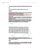
2). To solve this question, we need to consider the resistivities, lengths and cross-sectional areas of each of the wires. Resistivity (expressed by the symbol ?) is related to resistance by the following equation,
where ? is the resistivity of a given wire, R is the resistance of the wire, A is the cross-sectional area of the wire, and l is the length of the wire. Rearranging this equation, we can solve for resistance,
Additionally, the radius of a wire is defined to be half of its diameter. The cross-sectional area of a wire can therefore be determined by the equation,
where A is the cross-sectional area of the wire, r is the wire's radius, and d is the wire's diameter. This expression for cross-sectional area can be combined with the above expression for resistance to give the following equation,
Using the conversion factor 1 m = 1000 mm, we can express the diameters of the aluminum and copper wires in meters. The diameters of the aluminum and copper wires can then be expressed as,
( with significant figures applied)
where da is the diameter of the aluminum wire, and dc is the diameter of the copper wire.
We can then substitute the values for the lengths, diameters and resistivities of the wires given in the question into the above equation for resistance. The resistance of aluminum wire can be calculated to be,
ohm
(ohm with significant figures applied)
where Ra is the resistance of the aluminum wire, da is the diameter of the aluminum wire, ?a is the resistivity of the aluminum wire, and la is the length of the aluminum wire. We can perform a similar set of calculations for the copper wire.
ohm
(ohm with significant figures applied)
where Rc is the resistance of the copper wire, dc is the diameter of the copper wire, ?c is the resistivity of the copper wire, and lc is the length of the copper wire.
Therefore, the difference in the end-to-end resistance of the aluminum and copper wires can be obtained by subtracting the individual resistances. Mathematically, this can be expressed as
ohm
ohm
(ohm with significant figures applied)
where Rdifference is the difference in the end-to-end resistance of the aluminum and copper wires.
3).
a). The 40 kg load applied to the aluminum and steel wires provides an applied force to each of these wires due to gravity. This force can be determined by the following equation,
where Fg is the force due to gravity, M is the mass of the applied load, and ag is the acceleration due to gravity. This acceleration is typically assumed to be equal to 9.8 m/s2 at the surface of the earth. Assuming that the steel and aluminum wires are located at the surface of the earth, we can use the above formula to calculate the gravitational force applied to the aluminum wire.
(with significant figures applied)
where Fga is the gravitational force applied to the aluminum wire, Ma is the mass of the aluminum wire, and ag is the acceleration due to gravity. We can calculate the gravitational force applied to the steel wire in a similar fashion.
(with significant figures applied)
where Fgs is the gravitational force applied to the steel wire, Ms is the mass of the steel wire, and ag is the acceleration due to gravity.
The stress applied to a material (typically represented by the symbol ?) is mathematically defined as,
where F is the force applied to the material in question, and A is the material's cross-sectional area.
The strain that a material undergoes (typically represented by the symbol ?) is defined as its fractional deformation. Mathematically, this is expressed as,
where lf is the final length of the material after deformation, and l0 is the initial length of the material before deformation.
In the elastic region of the stress-strain curve, there is a linearly proportional relationship between stress and strain. This constant of proportionality is the modulus of elasticity. In the elastic region of the stress-strain curve, removal of the applied stress will cause the material to return to its original dimensions. Mathematically, this relationship in the elastic region of the stress-strain curve can be expressed by the following formula,
where Y is the modulus of elasticity of the material, ? is the stress applied to the material, and ? is the strain the material undergoes.
From question 2, we know that the cross-sectional area of a wire can be determined to be,
where A is the cross-sectional area of the wire and d is the wire's diameter.
The stress applied to each wire can then be expressed by the formula,
Using the conversion factor 1 m = 1000 mm, we can express the diameters of the wires in meters. The diameter of the steel wire can then be expressed as
( with significant figures applied)
where da is the diameter of the aluminum wire, and dc is the diameter of the copper wire. The stress applied to the steel wire is therefore,
( with significant figures applied)
where ?s is the stress applied to the steel wire, 1 Pa = 1 kg / (m*s2), and 1MPa = 1x10⁶ Pa.
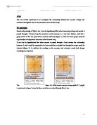
The yield strength of a material is the stress at which the elastic region of the stress-strain curve begins and initial plastic deformation occurs. When plastic deformation occurs, removal of the applied stress will not cause the material to return to its original dimensions. Since ?s = 630.1097103 MPa is less than the yield strength of steel (980 MPa), the 40 kg applied load is deforming steel within its elastic region. We can therefore use the modulus of elasticity of steel to relate the stress applied to the steel wire to its resultant strain.
Rearranging the above equation involving modulus of elasticity, stress and strain, we can express strain as,
Using the conversion factor 1 GPa = 1000 MPa, we can express the modulii of elasticity of the wires in MPa. The modulii of elasticity of the wires can then be expressed as
( with significant figures applied)
( with significant figures applied)
where Ys is the modulus of elasticity of the steel wire, and Ya is the modulus of elasticity of the aluminum wire.
Therefore, the strain that the steel wire experiences can be expressed as,
( with significant figures applied)
where ?s is the strain experienced by the steel wire.
The question states that the elastic deformation experienced by the steel wire (which is equal to the strain in the elastic region) must be the same as the elastic deformation experienced by the aluminum wire. Therefore,
( with significant figures applied)
where ?a is the strain experienced by the aluminum wire.
Rearranging the above relationship between stress, strain and modulus of elasticity, we can calculate the stress applied to the aluminum wire as,
(with significant figures applied)
where ?a is the stress applied to the aluminum wire. Since ?a = 215.159413 MPa is less than the yield strength of aluminum (255 MPa), the 40 kg applied load is deforming aluminum within its elastic region. We are therefore justified in using the modulus of elasticity of aluminum to relate the stress applied to the aluminum wire to its resultant strain.
The diameter of the aluminum wire can therefore be determined by rearranging the above equation relating stress, diameter and applied force. Therefore,
( with significant figures applied)
where da is the diameter of the aluminum wire.
The volume of each of the wires can be determined by the following formula,
where V is the volume of the wire and l is the length of the wire. Therefore, the volumes of the steel and aluminum wires can be calculated to be,
m3
(m3 with significant figures applied)
m3
(m3 with significant figures applied)
where Vs is the volume of the steel wire, Va is the volume of the aluminum wire, and ls is the length of the steel wire, and la is the length of the aluminum wire.
The mass of the wires can be determined by the following formula,
where M is the mass of a given wire, V is the volume of the wire, and D is the density of the wire. Therefore, the masses of the steel and aluminum wires can be calculated to be,
( with significant figures applied)
( with significant figures applied)
where Ms is the mass of the steel wire, Ma is the mass of the aluminum wire, Ds is the density of the steel wire, Da is the density of the aluminum wire, Vs is the volume of the steel wire, and Va is the volume of the aluminum wire. The question states that the lengths of the two wires are the same, so
Therefore, the aluminum wire is a certain percent heavier or lighter than the steel wire. This percentage can be calculated by,
( with significant figures applied)
Thus, the aluminum wire is 0.7279345% heavier than the steel wire. With significant figures applied, the aluminum wire is 0.7% heavier than the steel wire.
b).
The force applied to each wire, again under the assumption that the wires are located at the surface of the earth, is given as,
where Fga is the gravitational force applied to the aluminum wire, Ma is the mass of the aluminum wire, Fgs is the gravitational force applied to the steel wire, Ms is the mass of the steel wire, and ag is the acceleration due to gravity.
The maximum stress that each wire can have applied to it without undergoing plastic deformation is equal to its yield strength. This yield strength can be expressed as
where YS is the yield strength of the material in question, F is the force applied to that material, and A is its area. Rearranging this equation to solve for force, we can express the forces applied to each of the wires as
where YSs is the yield strength of the steel wire, YSa is the yield strength of the aluminum wire, As is the cross-sectional area of the steel wire, and Aa is the cross-sectional area of the aluminum wire. From the equation in part a relating diameter and cross-sectional area,
where ds is the diameter of the steel wire, and da is the diameter of the aluminum wire. The question states that the both wires must undergo the same maximum load without deforming. Therefore, the forces applied to both loads must be the same, so
Thus,
We know from the question that YSs = 980 MPa, YSa = 255 MPa, and ds = 8.9x10⁻⁴ m. Thus, we can solve for da by rearranging the above equation,
( with significant figures applied)
Therefore, the volumes of the steel and aluminum wires can be calculated to be,
m3
(m3 with significant figures applied)
m3
(m3 with significant figures applied)
where Vs is the volume of the steel wire, Va is the volume of the aluminum wire, and ls is the length of the steel wire, and la is the length of the aluminum wire.
The mass of the wires can be determined by the formula in part a. Therefore, the masses of the steel and aluminum wires can be calculated to be,
( with significant figures applied)
( with significant figures applied)
where Ms is the mass of the steel wire, Ma is the mass of the aluminum wire, Ds is the density of the steel wire, Da is the density of the aluminum wire, Vs is the volume of the steel wire, and Va is the volume of the aluminum wire. The question states that the lengths of the two wires are the same, so
Therefore, the aluminum wire is a certain percent heavier or lighter than the steel wire. This percentage can be calculated by,
( with significant figures applied)
Thus, the aluminum wire is 32.1843387% heavier than the steel wire. With significant figures applied, the aluminum wire is 30% heavier than the steel wire.
c).
As in part b, the force applied to each wire, again under the assumption that the wires are located at the surface of the earth, is given as,
where Fga is the gravitational force applied to the aluminum wire, Ma is the mass of the aluminum wire, Fgs is the gravitational force applied to the steel wire, Ms is the mass of the steel wire, and ag is the acceleration due to gravity.
The maximum stress that each wire can have applied to it without breaking is equal to its tensile strength. A given wires will not necessarily break when the stress equal to the tensile strength is applied. However, when stress equal to the tensile strength is applied, necking begins. Prior to necking, an increase in stress causes the material to undergo a uniform thinning as it is deformed. However, at the onset of necking, the material will begin to thin in over a localized portion. After this point, increasing the strain, or fractional deformation, experienced by the material will not cause the stress to rise. Eventually, if the strain is further increased, the material will break. However, the maximum stress that can ever be applied to the material is equal to its tensile strength. This tensile strength can be expressed as
where TS is the tensile strength of the material in question, F is the force applied to that material, and A is its area. Rearranging this equation to solve for force, we can express the forces applied to each of the wires as
where TSs is the tensile strength of the steel wire, TSa is the tensile strength of the aluminum wire, As is the cross-sectional area of the steel wire, and Aa is the cross-sectional area of the aluminum wire. From the equation in part a relating diameter and cross-sectional area,
where ds is the diameter of the steel wire, and da is the diameter of the aluminum wire. The question states that the both wires must undergo the same maximum load without deforming. Therefore, the forces applied to both loads must be the same, so
Thus,
We know from the question that TSs = 1130 MPa, TSa = 400 MPa, and ds = 8.9x10⁻⁴ m. Thus, we can solve for da by rearranging the above equation,
( with significant figures applied)
Therefore, the volumes of the steel and aluminum wires can be calculated to be,
m3
(m3 with significant figures applied)
m3
(m3 with significant figures applied)
where Vs is the volume of the steel wire, Va is the volume of the aluminum wire, and ls is the length of the steel wire, and la is the length of the aluminum wire.
The mass of the wires can be determined by the formula in part a. Therefore, the masses of the steel and aluminum wires can be calculated to be,
( with significant figures applied)
( with significant figures applied)
where Ms is the mass of the steel wire, Ma is the mass of the aluminum wire, Ds is the density of the steel wire, Da is the density of the aluminum wire, Vs is the volume of the steel wire, and Va is the volume of the aluminum wire. The question states that the lengths of the two wires are the same, so
Therefore, the aluminum wire is a certain percent heavier or lighter than the steel wire. This percentage can be calculated by,
( with significant figures applied)
The aluminum wire must be (100 - 97.16560511)% lighter than the steel wire. Performing this subtraction, the aluminum wire is 2.834394895% lighter than the steel wire. With significant figures applied, the aluminum wire is 3% lighter than the steel wire.
REFERENCES
Ball, P. 1997. Made to Measure, Princeton.
Callister, WD. 1997. Materials Science & Engineering: an Introduction, Wiley, New York.
Courtney, TH. 1990. Mechanical Behavior of Materials. McGraw Hill.
Hertzberg, RW. 1996. Deformation and Fracture Mechanics for Engineering Materials. Fourth Edition. Wiley, New York.
Materials Science and Engineering Laboratory : NIST. 2003. http://www.msel.nist.gov/.
McClintock, F and Argon, AS. 1966. Mechanical Behavior of Materials, Addison Wesley.
Smith, WF. 1996. Principles of Materials Science and Engineering, McGraw-Hill.
Van Vlack, LH. 1989. Elements of Materials Science and Engineering, Addison-Wesley 6th ed.
Weast, RC (editor). 1985. CRC Handbook of Chemistry and Physics, CRC Press, Inc. Boca Raton, FL.