With diagrams compare and contrast the relative advantages and disadvantages of digital transmission over analogue transmission in modern communication systems
With diagrams compare and contrast the relative advantages and disadvantages of digital transmission over analogue transmission in modern communication systems.
There are main types of transmission that are used by two different forms of signals from one computer to another computer and they are:
> Analogue Transmission
> Digital Transmission
Analogue Transmission
An analogue transmission has no break in the signal and the movement along the sine wave will never stop. So therefore the analogue transmission is continuous. The waves fluctuate (rise or fall) a certain amount of times per unit of time this type of fluctuation over time is called frequency. Frequency is measured in hertz, this means the large amount of fluctuations the higher the frequency. The frequency will then translate into higher notes. The low frequency will produce low deep notes. This signal also fluctuates in its loudness. The loudness is called amplitude. A low volume has low amplitude. In analogue transmission the physical quantity of the signal carrying the information through (amplitude, frequency, and phase) varies in a direct relationship to the information to be transmitted.
Advantage of Analogue Transmission
The advantage of analogue transmission that it has no break in the signal and it's always continuous.
Disadvantage of Analogue Transmission
The disadvantage of analogue transmission is that the noise enters when the wave travels. This can cause a loss of quality at the other end of transmission this is because the analogue signal can't be transmitted over a long distance. The signal becomes weaker the further the wave has to travel. This means the signal has to be boosted or amplified at regular intervals if it has to be transmitted very far.
Digital Transmission
Computers are digital machines because at their most basic level they can tell apart between just two values, that are 0 and 1, or off and on. This has been describes any system based on discontinuous data or events. There is no simple way to represent all the values in between, such as the value of 0.25. All data that a computer processes must be encoded digitally, as a series of zeroes and ones. The opposite of a digital is an analogue.
Advantages of Digital Transmission
The advantage of a digital transmission is that the signal is always exact, and also can be checked if it has any errors, the noise or the interference can be easily filtered out. There are a variety of services can be offered over one line, also Digital signal can be processed very fast.
Disadvantages of Digital Transmission
Digital transmission system uses a different in Frequency, Amplitude and how it represents a binary data analogue transmission. This can't transfer the analogue signals because of the speed that release on a form of a message.
This line of the diagram below represents one specific point on an analogue wave. The measurements have been taken continuously and very rapidly from the analogue signal. A computer uses only digital signals. In order to be able to transfer digital data over conventional analogue transmission media such as phone lines, all signals must be converted to analogue. The process of converting digital to analogue is called modulation. Of course, at the other end, the signal must be changed back to digital. This is called demodulation. A device called a Modem is used to do this. Modem is short for Modulator/Demodulator.
Name and describe two examples of information, which are commonly transmitted in digital form, but are presented to users in analogue form. Use the diagram to show how this information is transformed and transmitted as a digital signal.
Example One:
Most of the computers are digital devices. Therefore, any signals and data from an analogue device must be passed through a suitable analogue-to-digital converter before they can be received and processed by computer. The monitors are analogue, so the data or the information before they can be presented to the user they converted to analogue. This is an example of the diagram shown below:
Example Two:
Another example is mobile phone, which is used to transmit and receive voice signals this is before the voice signals can be transmitted, it must be changed into a form that is suitable for transmissions. It must first undergo a process of conversion from analogue to digital form. It then must be compressed so that it can be transmitted efficiently. Before the signal is finally sent into the air, it must be tailored so that it travels effortlessly through the air medium. At the receiver similar manipulations of the signal in reverse order needs to be applied so that the original voice signal can be recovered. All the manipulations of the signal use techniques and technology from DSP. I have inserted an image of the mobile phone with some of annotations; I have also inserted a diagram showing voice signals being transferred into digital form whilst speaking through the telephone:
Image One:
Diagram One:
A small microphone in the mouthpiece of the telephone handset captures the speaker's voice through a vibrating diaphragm; this creates variations in the electrical current flowing through the microphone. These electrical signals are transmitted through the telephone lines, and played on the vibrating diaphragm of the receiver part of the listener's handset.
Describe briefly with a diagram what a modem is. Explain the role of a modem in the transmission of computer data over analogue sections of the Public Switch Telephone Network (PSTN). Briefly explain and suggest organizations and application which would be likely to use:
> Leased lines
> Dial-up connections
To access external networks. Justify your choice in each case.
What is a modem?
Modulator-demodulator - a device or program that enables a computer to transmit data over analogue telephone lines. Computer information is stored digitally, whereas information transmitted over telephone lines is transmitted in the form of analogue waves. A modem converts between these two forms.
The role of the modem to transmit and receive digital data over a communications line normally used for analogue signals. A modem attached to a computer converts digital data to an analogue signal that it uses to modulate a carrier frequency. This frequency is transmitted over a line, frequently as an audio signal over a telephone line, to another modem that converts it back into a copy of the original data.
Types of Modem
There are two main types of modems and they are:
> External Modem
> Internal Modem
External Modem
This is the simplest type of modem device to install because you don't have to open the computer. External modems have their own power supply and connect with a cable to a computer's serial port. The telephone line plugs into a socket on the rear panel of the modem. The diagram shown below:
Internal Modem
Most internal modems come installed in the computer you buy. Internal modems are more integrated into the computer system and you do not need any special attention. Internal modems are activated when you run a communications program and are turned off when you exit the program. This convenience is especially useful for novice users. These types of modems usually cost less. This is a diagram I have shown below of an internal modem.
The PSTN stands for Public Switch Telephone Network, this was designed for voice transmission only, and using analogue electrical signals to represent what is spoken and heard at each end of a link. A telephone mouthpiece contains a diaphragm, which vibrates whenever it is struck by sound waves, and these vibrations are converted to electrical signals (digital signals) by a modem, which have direct link to what is said.
Leased Lines
A leased line connection is a wide area network that offers fast, reliable connection for all data traffic. Leased line is has a permanent and good connection to the Internet that brings enhanced Internet performance and reliability. The high-priced call charges of ISDN and the insufficiencies of the standard dial-up connection mean that leased line service is the cost-effective alternative, supplying your business with a high-speed connection at a fixed annual price. With no call or usage charges, you pay upfront for unlimited use.
All types of organisations are serious about their Internet access use Leased Lines. In today's business environment the Internet has become an essential communication, information, and marketing tool, this may needs to be available all of the time. Many companies might lose money if they could not receive orders or e-mails so they need the guarantee of a Service Level Agreement (SLA). This means that should their connection be down longer than the time allowed in the SLA they would receive service credits as compensation.
A leased line will give the customer a complete direct connection from their network straight into one of Onyx Internet's Points of Presence (POP), this type of service provides a fast link out onto the Internet.
Leased Lines are suitable for heavy Internet users and they can easily be upgraded as Internet usage or traffic flow increases. This diagram below shows how a leased line will provide your network with a fast link out to the Internet:
Dial-up connections
A dial-up connection uses the public telephone network and the user only pays for the time taken for transmission. Alternatively, other nodes may require the link for most of the working day, in which case a permanent leased line is appropriate. Leased lines provide a more reliable transmission medium and also allow higher speeds of data transmission.
Dial-up connections are cheaper, but support lower transmission rates than leased lines. They are more cost effective than leased lines for low-volume work and allow the operator to choose the destination of transmissions.
Describe the main functions of a communication protocol.
Communication protocol
Protocols are basically sets of rules that enable how two of the devices should communicate. Protocols are used for modem communications, usually between a home and a business user and Internet service provider's server (ISP). Computers must use the same modem protocols and setting if they are to communicate reliable, when sending and receiving data. For example if a modem is set to use 8 data bits, and the other one 1-stop bit. The modem in this case will not be able to understand the data unless it uses the same setting and also both modems must have the same speed operating. Therefore when connecting to the Internet, the connect speed could be different. The connect speed is depending on the modem speed at the Internet Service Provider's site, once the dial-up connecting is been made. For communication between two devices, the protocol must set up as a minimum:
> Data transmission rate must be measured in bits per seconds, if the devices have different maximum transmission rates. The rate will allow dictating the slower of the two devices.
> The protocol must decide which device is currently has control of the communication link. If the two devices may transmit to each other at the same time or one direction at a time.
> If the synchronous, (which send data in a stream with sender and receiver synchronised to identify when one character ends and another stars) or asynchronous (which characters are sent at regularly timed intervals, with star and stop bits to separate characters) transmission is to be used.
The Protocols specify the form of handshaking, the method of data flow control and mechanisms for error control and data compression.
Aloha is a protocol for satellite and terrestrial radio transmissions. In pure Aloha, a user can transmit at any time but risks collisions with other users' messages. "Slotted Aloha" reduces the chance of collisions by dividing the channel into time slots and requiring that the user send only at the beginning of a time slot. Aloha was the basis for Ethernet, a local area network protocol.
Aloha is also called the Aloha method this refers to a simple communications scheme in which each source (transmitter) in a network sends data whenever there is a frame to ...
This is a preview of the whole essay
Aloha is a protocol for satellite and terrestrial radio transmissions. In pure Aloha, a user can transmit at any time but risks collisions with other users' messages. "Slotted Aloha" reduces the chance of collisions by dividing the channel into time slots and requiring that the user send only at the beginning of a time slot. Aloha was the basis for Ethernet, a local area network protocol.
Aloha is also called the Aloha method this refers to a simple communications scheme in which each source (transmitter) in a network sends data whenever there is a frame to send. If the frame successfully reaches the destination (receiver), the next frame is sent. If the frame fails to be received at the destination, it is sent again. This protocol was originally developed at the University of Hawaii for use with satellite communication systems in the Pacific.
In a wireless broadcast system or a half-duplex two-way link, Aloha works perfectly. But as networks become more complex, for example in an Ethernet system involving multiple sources and destinations that share a common data path, trouble occurs because data frames collide (conflict). The heavier the communications volume, the worse the collision problems become. The result is degradation of system efficiency, because when two frames collide, the data contained in both frames is lost. Diagram is shown below:
With a diagram briefly explain the concept of handshaking and flow control and state why they are a necessary part of data communication.
Handshaking means that communicating devices must have a common method of determining their presence and readiness in order to communicate. Although the details vary, a handshake can be illustrated simply by the following example. Suppose that device A wishes to communicate with device B. Device A signals "Hello Device B, are you there?" to which device B repliers, "Yes, I am here A." Finally, device A responds," I see that you are there B." The handshake should also define when each device has finished sending or receiving a message.
A flow control is a mechanism that is needed to ensure that data transmission flows smoothly, that the communications channel is not overloaded and that the transmitting device does not send data more quickly than the receiver handle.
Identify two methods of error checking in data transmission and explain how they help to maintain the integrity of a data transmitted.
The two methods of error checking in data transmission I will analyse will be the following:
> CRC (Cyclical Redundancy Checking)
> Parity Bit
Method One:
CRC stands for Cyclical Redundancy Checking this is an error checking technique that is used to ensure the accuracy of transmitting digital data. The transmitted messages are divided into predetermined lengths that are used as dividends, are divided by a fixed divisor. The remainder of the calculation is appended onto and sent with the message. At the receiving end, the computer recalculates the remainder. If it does not match the transmitted remainder, an error is detected.
Method Two:
In computers, Parity (from the Latin parities: equal or equivalent) refers to a technique of checking whether the data has been lost or it has written over when it's been moved from one place in storage to another or when transmitted between the computers.
The method works by an additional binary digit, the parity bit, is added to a group of bits that are moved together. This bit is used only for the purpose of identifying whether the bits being moved arrived successfully. Before the bits are sent, they are counted and if the total number of data bits is even, the parity bit is set to one so that the total number of bits transmitted will form an odd number. If the total number of data bits is already an odd number, the parity bit remains or is set to 0. At the receiving end, each group of incoming bits is checked to see if the group totals to an odd number. If the total is even, a transmission error has occurred and either the transmission is retried or the system halts and an error message is sent to the user.
Distinguish between packet, circuited and message switching.
Packet-switched are describes the type of network in which relatively are in small units of data called packets they are routed through a network based on the destination address which contained within each packet. Breaking communication down into packets allows the same data path to be shared among many users in the network. This type of communication is between the sender and the receiver is known as connectionless (rather than dedicated)
Contrasted with packet-switched is circuit-switched, a type of network such as the regular voice telephone network in which the communication circuit (path) for the call is set up and dedicated to the participants in that call. For the duration of the connection, all the resources on that circuit are unavailable for other users. Voice calls using the Internet's packet-switched system are possible. Each end of the conversation is broken down into packets that are reassembled at the other end.
The principles of packet switching are as follow. Messages are divided into data packets, which are then directed through the network to their destination under computer control. Besides a message portion, each packet contains data concerning.
The principles of packet switching are as follow. Messages are divided into data packets, which are then directed through the network to their destination under computer control. Besides a message portion, each packet contains data concerning:
> The destination of the address;
> The source identification;
> The sequence of the packet in the complete message;
> The detection and control of transmission errors.
> Pre-determined routing. With this method, the routing details are included in the packet itself, each switching exchange forwarding the packet according to the embedded instructions;
> Directory routing. Each switching exchange has a copy of a routing table to which it refers before forwarding each packet. The appropriate output queue is determined from the table and the packet destination
Diagram shown below:
Identify three types of cabling used in data communication. State which one you would recommend in an implement requiring high security consideration and why?
The three types of cables used in data communication are:
> Coaxial
> UPT
> Optical Fiber
Coaxial
Coaxial cable is a copper that is used by TV companies between the community antenna, and also the user homes and businesses. At times these cable are also used by telephone companies from their central office to the telephones near users. This is also widely installed for use in business and corporation Ethernet and other types of local area network.
Coaxial cable is called "coaxial" this is because this includes one physical channel that carries the signal surrounded (after a layer of insulation) by another concentric physical channel, both running along the same axis. The outer channel serves as a ground. Many of these cables or pairs of coaxial tubes can be placed in a single outer sheathing and, with repeaters, they can carry information for a great distance. This is a diagram shown below:
UPT
UPT stands for Unshielded twisted pair. This cable is the most common kind of copper telephone wiring. Twisted pair is the ordinary copper wire that connects home and many business computers to the telephone company. To reduce crosstalk or electromagnetic induction between pairs of wires, two insulated copper wires are twisted around each other. Each signal on twisted pair requires both wires. Since some telephone sets or desktop locations require multiple connections, twisted pair is sometimes installed in two or more pairs, all within a single cable. For some business locations, twisted pair is enclosed into a shield that functions as a ground. This is known as shielded twisted pair (STP).
The twisted pair is now frequently installed with the two pairs to the home, with the extra pair making it possible for you to add another line (perhaps for use of a modem) when you will need it.
These twisted pair comes with each pair uniquely colour coded when it is packaged in multiple pairs. Different uses such as analogue, digital, and Ethernet require different pair multiples.
Although twisted pair is often associated with home use, with a higher grade of twisted pair is often used for horizontal wiring in LAN installations because it is less expensive than coaxial cable.
The wire that you buy at a local hardware store for extensions from your phone or computer modem to a wall jack is not twisted pair. It is a side-by-side wire known as silver satin. The wall jack can have as many five kinds of hole arrangements or pin outs, depending on what kinds of wire the installation you expects that will be plugged in (for example, digital, analogue, or LAN) . (That's why you may sometimes find when you carry your notebook computer to another location that the wall jack connections won't match your plug.) This is a diagram shown below:
Optical Fiber
Optical fiber (or "fiber optic") refers to the medium and the technology associated with the transmission of information as light pulses along a glass or plastic wire or fiber. Optical fiber carries much more information than the conventional copper wire and is in general not subject to electromagnetic interference and the need to retransmit signals. Most telephone company long-distance lines are now of optical fiber.
Transmission on optical fiber wire requires repeaters at distance intervals. The glass fiber requires more protection within an outer cable than copper. For these reasons and because the installation of any of the new wiring is labour-intensive, few communities yet have optical fiber wires or cables from the phone company's branch office to local customers (known as local loops).
A type of fiber known as single mode fiber is used for longer distances; multimode fiber is used for shorter distances. This is the diagram shown below:
By analyzing and researching the three above cable I would recommend the Fiber Optic cable this is because I believe it has a high security and also has the following:
> Fiber optic cables have a much greater bandwidth than metal cables. This means that they can carry more data.
> Fiber optic cables are less susceptible than metal cables to interference.
> Fiber optic cables are much thinner and lighter than metal wires.
> Data can be transmitted digitally (the natural form for computer data) rather than analogically.
Identify the alternative forms of communication media and provide examples of their use in different forms of network.
Microwave
Microwave frequencies require a direct line of sight between sending and receiving station to operate. Microwave systems were the preferred method of communications transmission before the introduction of fiber optic.
Radio
The lowest-frequency domain that needed to name. This extends from wavelengths of a kilometre or so, the longest that will propagate through the interstellar medium, down to about a millimetre. The detection of radio radiation is often done using wave techniques rather than photon-counting, this is because of the low photon energies, and this offers distinct advantages for such applications as interferometer which astronomers working in the infrared and optical regimes view with some envy. From active nuclei, we often detect the synchrotron radiation in this range - radiation produced energetic charged particles (mostly electrons) produce when they are deflected by the magnetic fields.
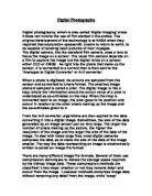
a) Define the basic signal theory with the aid of diagrams?
) In electronics, a signal is an electric current or electromagnetic field that is used to convey data from one place to another. The simplest form of signal is a direct current (DC) that is switched on and off; this is the principle by which the early telegraph worked. More complex signals consist of an alternating-current (AC) or electromagnetic carrier that contains one or more data streams.
Data is superimposed on a carrier current or a wave this is by means of a process called a modulation. Signal modulation can be done by two main ways: analogue and digital. In recent years, digital modulation has been getting more common, while analogue modulation methods have been used less and less. There are still plenty of analogue signals around, however, and they will probably never become totally extinct.
Except for DC signals such as telegraph and base band, all signal carriers have a definable frequency or frequencies. Signals also have a property called wavelength, which is inversely proportional to the frequency.
2) In some information technology contexts, a signal are simply "that which is sent or received," thus including both the carrier and the data together.
3) In telephony, a signal has a special data that is used to set up or control communication.
Almost everything in the world can be described or represented in one of two forms: analogue or digital. The principal feature of analogue representations is that they are continuous. In contrast, digital representations consist of values measured at discrete intervals.
Digital watches are called digital because they go from one value to the next without displaying all intermediate values. Consequently, they can display only a finite number of times of the day. In contrast, watches with hands are analogue, this is mainly because the hands move continuously around the clock face. As the minute hand goes around, it not only touches the numbers 1 through 12, but also the infinite number of points in between.
Early attempts at building computers used analogue techniques, but the accuracy and reliability were not good enough. Today, almost all computers are digital.
Analogue and Digital Technology
Analogue and Digital are the words we hear when people talk about Communication and Information Technology.
What do the words Analogue and Digital mean?
'Analogy' means a likeness between two things that are really quite different. For example the analogy between the brain and the computer or the heart and a pump.
Digit means either a finger or toe, or one of the numbers 1 to 9.
Some examples might help to explain what analogue and digital mean in technology.
A simple example of analogue and digital technology
Clocks are examples of analogue and digital technology. An analogue clock face can display the time without numbers. The hands keep moving all the time and they continue to rotate, just like the earth around the sun.
This is the analogy between the movement of the sun and earth, and the hands of the clock.
The digital clock displays the time in numbers, and the time displayed only changes at each minute. In the analogue clock the hands keep moving all the time, while the digital clock is more like an on and off movement. Each minutes the time moves and then stops for another 60 seconds, when it changes again.
Some other examples of displaying information using analogue and digital forms.
b) How the signal theory affects the choice of transmission methods and media?
Analogue and Digital Signals
Sound can be converted into analogue and digital electrical signals.
Analogue Signal
A microphone or handset of a telephone will convert sound into an analogue signal. The shape of the wave seen on an oscilloscope represents the volume and pitch. The diagram is shown below:
This is called an analogue signal because, when the volume and pitch change, so does the shape of the wave. The signal is an analogue of the sound.
Digital signal
Today we see many sound systems described as digital. This means the sound is converted into digital signals so it can be transmitted or recorded. In the microphone example shown on the diagram above, the analogue signal is converted into a digital signal by electronic circuits. In a digital signal the electricity, this can be either on or off, is combined with a binary code.
The voltage of the analogue signal is measured electronically, many thousands of times per second, by an analogue-digital converter. The analogue signal is converted into a 16 bit binary number, which gives 65,536 levels of voltage.
In electronics 1 = ON and 0 = OFF. This means the binary number can be converted into an electrical signal.
A diagram below shows the process of converting analogue signals into a binary numbers and digital signals. To keep the explanation simple the analogue signal has been converted into a 3 bit binary number, which means there are seven voltage levels.
A digital-analogue converter reverses the conversion this is because the speakers (output device) need an analogue signal.
Light and sound can be converted into binary numbers and digital signals that are used to record and transmit information. This diagram is shown below:
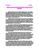
Why are digital systems better than the analogue ones?
An analogue signal is affected by changes in the voltage as it travels along a wire. If the voltage changes, so does the signal at the output. The digital signal is not affected by changes in the voltage this is because all that matters is whether it is ON or OFF.
How signal affects transmission methods?
Noise is any sound on the CD or record that wasn't there at the performance during the recording session. More generally, it is any unwanted signal that adds on to the information that is being transmitted. When a vinyl record is being made, noise is introduced at every step of the recording process, although of course the company makes an every effort to reduce such noise to as low a level as possible. The sound that reaches the microphones is converted into an electrical signal that is then recorded on a wide magnetic tape moving at high speed. This tape is then used to control the cutting of a master disc, from which moulds are then made. These in turn are used to mass-produce the records that are eventually sold in shops. Noise is produced at every step, not forgetting that introduced by your own stereo equipment. It can never be entirely eliminated.
The same problems of noise are shared by any method of transmitting information, and are certainly by telecommunications, including telephone calls.
In the production of vinyl records, the companies have used purely analogue this means to transfer the information representing the sound of the music from one point to another. That means they use an electrical signal that changes smoothly in strength, exactly modelling the smooth but complex changes in the sound.
When a noise is created in the recording process - because of tape hiss, dust on the master disc, electrical interference or any other cause - this is added on as a random signal on top of the complex electrical signal representing the sound. There is no way that electronic equipment can tell such random noise from the original electrical signal, so there is no way it can be removed again without removing some of the original signal.
We can see more clearly if we draw a graph of the level of the analogue audio signal over a period of time (diagram 1a). The shape of this graph represents both the changes in the electrical sound and the changes in the electrical signal that model it. Now if we add to this audio signal some random noise, this affects the shape of the signal, and this degrades the sound that your stereo reproduces (diagram 1b).
The trouble with an analogue audio signal is that its exact shape has to be preserved if you are to hear the music exactly as it was when it was played. If there were a means of transmitting the signal so that only the overall shape of the signal mattered, then noise would not be so important.
The port authorities used to find the shape of the bottom of the harbour, so that ships could navigate more safely. It certainly wasn't possible to drain the harbour and take a photograph of it, so what they did instead was send out a boat which travelled slowly across the harbour. Every few meters a person at the back of the boat dropped down a plumb-line (a weight at the end of a rope), until it reached the bottom of the harbour. The line had knots tied in it at regular spaces and the person called out the number of knots under water, so indicating the depth of the harbour at that point. A clerk wrote these down, and eventually it was possible for him to draw a graph of the shape of the harbour by using these numbers.
The person in the boat had been taking samples of the depth of the harbour at frequent intervals, so that the graph would accurately describe the ups and downs of the harbour bottom. In just the same way, the electronic equipment used in pulse code a modulation that takes a sample of the level of the audio signal, and converts these measurements into numbers, or digits. (See the diagram below) It is important to note at this point that because the measurement is represented by a limited number of digits, there may be some slight loss of accuracy (in our analogy, the depth of the harbour is indicated by whole numbers of knots under water, not by fractions or parts of the distance between knots).
These numbers are then coded into a series of on-or-off electrical pulses (in some systems they may be strictly high-or-low pulses), in very much the same way that letters of the English language were coded into the dots and dashes of Morse code. These pulses are then transmitted.
Now, although noise will still occur during this transfer of the information, exactly as it does in analogue transmission, it has little effect unless the noise level is very high. The reason for this is that now the receiving device only has to examine the incoming signal to determine if a pulse is present at a particular moment or not. The exact level of the signal is not important at all, so long as an "on" condition can still be clearly obvious from an "off" condition. (See diagram below) The original signal can then be reconstructed exactly.
However, we must remember that the information is transmitted by digital methods. This can only approximate the original analogue sound. There are two of the reasons for this. Firstly, as we have mentioned, the level of the audio signal can only be represented by a limited number of digits, restricting the accuracy with which it can be measured. Secondly, the original signal is only sampled at the end of discrete intervals of time, and we know nothing of what is happening to the signal between these intervals. For this reason, the sampling must take place at very short intervals.
Compare and contrast the following communication channels:
a) Time Division Multiplexing (TDM)
b) Frequency Division Multiplexing (FDM)
c) Wave Division Multiplexing (WDM)
Time Division Multiplexing (TDM)
Time-division multiplexing (TDM) is a method of putting multiple data streams into a single signal by separating the signal into many segments, each having a very short duration. Each of the individual data stream is reassembled at the receiving end based on the timing.
The circuit that combines signals at the source (transmitting) end of a communications link is known as a multiplexer. This accepts the input from each individual end user, breaks each signal into segments, and assigns the segments to the composite signal in a rotating, repeating sequence. The composite signal therefore contains data from multiple senders. At the other end of the long-distance cable, the individual signals are separated out by means of a circuit called a demultiplexer, and this has routed to the proper end users. A two-way communications circuit requires a multiplexer/demultiplexer at each end of the long-distance, high-bandwidth cable.
If many signals must be sent along a single long-distance line, a careful engineering is required to ensure that the system will perform properly. An asset of TDM is its flexibility. The scheme allows for variation in the number of signals being sent along the line, and constantly adjusts the time intervals to make optimum use of the available bandwidth. The Internet is a classic example of a communications in network in which the volume of traffic can change drastically from hour to hour. In some systems, a different scheme, known as frequency-division multiplexing (FDM), that is preferred. Diagram below shows.
Time Division Multiplexing a type of multiplexing that combines data streams by assigning each stream a different time slot in a set. TDM repeatedly transmits a fixed sequence of the time slots over a single transmission channel. Within T-Carrier systems, such as T-1 and T-3, TDM combines Pulse Code Modulated (PCM) streams created for each conversation or data stream.
Frequency Division Multiplexing (FDM)
Frequency-division multiplexing (FDM) is a scheme that numerous signals are combined for transmission on a single of communications line or channel. Each signal is assigned a different frequency (sub channel) within the main channel.
A typical analogue Internet connection via a twisted pair telephone line requires approximately three kilohertz (3 kHz) of bandwidth for accurate and reliable data transfer. The Twisted-pair lines are common in households and small businesses. But major telephone cables, operating between large businesses, government agencies, and municipalities, are capable of much larger bandwidths.
A long-distance cable is available with a bandwidth allotment of three megahertz (3 MHz). This is 3,000 kHz, so in theory, it is possible to place 1,000 signals, each 3 kHz wide, into the long-distance channel. The circuit that does this is known as a multiplexer. It accepts the input from each individual end user, and generates a signal on a different frequency for each of the inputs. This results in a high-bandwidth, complex signal containing data from all the end users. At the other end of the long-distance cable, the individual signals are separated out by means of a circuit called a demultiplexer, and routed to the proper end users. A two-way communications circuit requires a multiplexer/demultiplexer at each end of the long-distance, high-bandwidth cable.
When FDM is used in a communications network, each input signal is sent and received at maximum speed at all times. This is its chief asset. However, if there is many signals must be sent along a single long-distance line, the necessary bandwidth is large, and careful engineering is required to ensure that the system will perform properly. In some systems, a different scheme, known as time-division multiplexing that is used instead. This is a diagram shown below:
Frequency Division Multiplexing is a multiplexing technique that uses different types of frequencies to combine multiple streams of data for transmission over a communications medium. FDM assigns a discrete carrier frequency for each data to stream and then combines into many modulated carrier frequencies for transmission. For example, television transmitters use FDM to broadcast several channels at once. Diagram shown below:
Wave Division Multiplexing (WDM)
In telecommunications wavelength division multiplexing (WDM) is multiplexing several optical carrier n signals on a single optical fibre by using different wavelengths (colours) of laser light to carry different signals.
Dense wave division multiplexing (DWDM) is generally held by WDM with more than 8 active wavelengths per fibre.
The device that joins the signals together is known as a multiplexor, and the one that splits them apart is a demultiplexor. With the right type of fibre you can have a device that does both.
The first WDM systems combined the two signals and appeared around 1985. Modern systems can handle up to 128 signals and then can expand into a basic of 9.6 Gbps fibre system to a capacity of over 1000 Gbps.
WDM systems are popular with telecommunications companies because they allow them to expand the capacity of their fibre networks without digging up roads again more than necessary which is extremely costly. All they have to do is to upgrade the (de)multiplexors at each end. However these systems are expensive and complicated to run.
Note that this term applies to an optical carrier (which is typically described by its wavelength), whereas frequency division multiplexing typically applies to a radio carrier (which is more often described by frequency). However, since wavelength and frequency are inversely proportional, and since radio and light are both forms of electromagnetic radiation, the distinction is somewhat arbitrary.
At times is called Dense wavelength division multiplexing (DWDM) is a technology that puts data from different sources together over a optical fiber, with each signal carried at the same time on its own separate light wavelength. Using DWDM, up to 80 (and in theory more) separate wavelengths or channels of the data can be multiplexed into a light stream transmitted on to a single optical fiber. Each of the channel carries a time division multiplexed (TDM) signal. In a system with each channel carrying 2.5 Gbps (billion bits per second), up to 200 billion bits can be delivered a second by the optical fiber. DWDM is also sometimes called wave division multiplexing (WDM).
Since each channel is demultiplexed at the end of the transmission back into the original source, different data formats being transmitted at different data rates can be transmitted together. Specifically, Internet (IP) data, Synchronous Optical Network data (SONET), and asynchronous transfer mode (ATM) data can all be travelling at the same time within the optical fiber. Diagram shown below:
Wavelength Division Multiplexing. A technology for transmitting multiple signals at the same time over a single optical fiber. The signals travel within colour bands, with one of the colour band for each signal. This diagram is shown below:
The comparison between the communication channels TDM, FDM, and WDM,
> How does WDM differ from FDM?
> FDM "Frequency Division Multiplexing"
In FDM the multiplexing is based on different frequencies. It is often said that FDM and WDM are the same thing. This is though not true while WDM is more of a part of FDM.
FDM can be used in coaxial cables for example but WDM can only be used in optical fibers. In WDM we mention about wave-lengths and in FDM about frequencies. When the frequency raises the wavelength gets smaller and smaller.
> How does WDM differ from TDM?
> TDM " Time Division Multiplexing"
In TDM the channel is divided into even-sized time-slots. These time-slots are then distributed between the slower channels.
If there are three channels a, b and c to be sent they can be divided into one channel for example as follows:
|-a-|-c-|-a-|-b-|-a-|-c-|-a-|-b-|-a-|
TDM is the technique used in today's optical fibers but will probably is changed to WDM.
Evaluate current transmission methods and media and assess suitability of each for a particular communications channel?
The transmission methods and media
Synchronous Serial Transmission
Synchronous serial transmission requires the sender and receiver share a clock with one another, or that the sender provide a strobe or other timing signal so that the receiver knows when to ``read'' the next bit of the data. In most forms of serial Synchronous communication, if there is no data available at a given instant to transmit, a fill character must be sent instead so that data is always being transmitted. Synchronous communication is usually more efficient this is because only data bits are transmitted between sender and receiver, and synchronous communication can be more costly if extra wiring and circuits are required to share the clock signal between the sender and receiver.
A form of Synchronous transmission is used with printers and fixed disk devices in that the data is sent on one set of the wires while a clock or strobe is sent on a different wire. Printers and fixed disk devices are not normally serial devices this is because most fixed disk interface with standards sends an entire word of data for each clock or strobe signal by using a separate wire for each bit of the word. In the PC industry, these are known as Parallel devices.
The standard serial communications hardware in the PC does not support Synchronous operations. This mode is described here for comparison purposes only.
As with asynchronous transmission it is apparent that the synchronous approach offers advantages to the transmission
> The amount of central information that requires to be transmitted is restricted to only a few characters at the start of each block.
> The system is not so prone to distortion as asynchronous communication and can therefore it can be used at higher speeds
The disadvantages of Synchronous
> If an error does occur the rather than just a single character the whole block of data will be lost.
> The sender cannot transmit characters simply as they might and consequently has to store them until it has built up a block, the system is unsuitable for applications where characters are generated at a irregular intervals.
Serial synchronous transmission is principally used for high-speed communication between computers.
Asynchronous Serial Transmission
Asynchronous transmission allows data to be transmitted without the sender having to send a clock signal to the receiver. Instead, the sender and receiver must agree on timing parameters in advance and special bits are added to each word, that are used to synchronize the sending and receiving units.
When a word is given to the UART for Asynchronous transmissions, a bit called the "Start Bit" is added to the beginning of each word that is to be transmitted. The control information consists of additional bits added to each character, START BITS- that indicates that transmission is about to commence - and STOP BITS-, which indicate that it is about to cease. The start Bit is used to alert the receiver that a word of data is about to be sent, and to force the clock in the receiver into synchronization with the clock in the transmitter. These two clocks must be accurate enough to not have the frequency drift by more than 10% during the transmission of the remaining bits in the word. (This requirement was set in the days of mechanical teleprinters and this is easily met by modern electronic equipment.)
The advantages of asynchronous transmission
> One principal advantage is that each individual character is complete in itself- therefore if a character is corrupted during the transmission, its successor and predecessor will be unaffected.
> Particularly suited for applications where the characters are generated at irregular intervals e.g. data entry from the keyboard.
The disadvantages of an asynchronous transmission system
> Successful transmission predictably depends on the recognition of the start bits, these can be easily missed, or occasionally spurious start bits can be generated by line interference.
> High proportions of the transmitted bits are uniquely for control purposes and therefore carry no useful information.
> As a result of the effects of distortion the speed of transmission is limited.
Asynchronous serial transmission is normally only used for speed of up to 3000 bits per second, with only simple, single-character error detection.
Transmission Media
Transmission media refers to the type of cable or wireless system that is used to connect network devices. Media options should be carefully considered when implementing a new LAN this is because it can make a significant impact on the cost, speed, and connectivity of the network. This diagram is shown below:
Types of transmission media
> Twisted Pair
> Coaxial cable
> Fibre Optic Cable
Guided Media
The three main types of cabling are generally used for guided transmission: twisted pair, coaxial cable and optical fibre. Each cable type has limitations as far as bandwidth and vulnerability to transmission impairments. This in turn places limits on the usable distance of cable runs and the data rate over those runs.
Twisted Pair
Twisted pair cable technology comes from the telephone industry. AT&T and others did a lot of research to develop a kind of cable that would be cheap to manufacture (since countless miles of it are needed to wire the nation's homes), have cheap but reliable connectors, be easy to work with, and have good transmission characteristics for voice communications. This diagram is shown below:
The twisted uses two pairs of insulated, solid copper wires, twisted about each other. The twists serve to limit the crosstalk between adjacent pairs, since usually there are between two and several hundred pairs bundled inside a single sheath. The simple, plastic connectors (RJ jacks and plugs) are also remarkably simple to use and inexpensive to manufacture. Twisted pair is commonly used to wire homes and businesses to the nearest telephone exchange and to wire private branch exchanges in businesses.
The excess of vendors and economies of scale on this cabling did not do unnoticed by the data communications industry that is quickly that is developed by various kinds of computer networks that could use the same media. 10 Base-T Ethernet is probably the most popular local area network, in part because of the low cost cabling.
Twisted pair comes in shielded and unshielded ("UTP") varieties. Typically UTP is used because it is cheaper and easier to work with, but it is more susceptible to electromagnetic interference from other cabling (power cabling, other UTP) and environmental noise (fluorescent lights, storms, transformers, etc.).
UTP is further divided into category 3 (CAT-3), CAT 4 and CAT 5 grades, each capable of supporting higher data rates and longer distances. Each of these is also available in plenum (fire-retardant) or non-plenum sheathing.
For point-to-point communications, twisted pair's bandwidth of 3 MHz allows the data rates up to 4 Mbps or more.
Twisted pair can be used for analogue signalling (e.g. voice), but it is mostly used with digital signalling in computer networks. Repeaters (digital signalling) are required every 2-3 km; amplifiers (analogue signalling) every 5-6 km.
The twisted pairs are commonly used for 10 Mbps Ethernet systems; 100 Mbps Ethernet is possible for distances up to 330 feet.
Coaxial Cable
The development of coaxial cable ("coax") as a data communications standard was largely driven by its widespread operation throughout the cable television industry. The economies of scale make it an attractive, low-cost option for computer networking, although it is more expensive than twisted pair.
Coax has two conductors: an outer braided cylindrical one surrounding an inner solid or stranded core. The two conductors that are separated by a dielectrics, insulating material and the cable has an outer protective sheath. This construction is electrically designed to minimize signal interference and attenuation, and in this regard coax is far superior to twisted pair. Coax also has much greater bandwidth (up to 350 MHz), so it can support higher data rates for longer distances.
Coax comes in a variety of types. The most commonly used in computer networks is RG-58, or "thin net". Thin net is very popular in Ethernet systems, although UTP (for short runs) and fibre (for long runs) has largely supplanted it in the LAN market. However, it is also used in many other proprietary LANs.
Coax can be used for both analogue and digital signalling. For point-to-point communications, data rates up to 500 Mbps or more are possible; repeaters are required every 2-3 km; amplifiers every 5-6 km.
Optical Fibre
The development of optical fibre for data communications is a huge breakthrough. Compared to twisted pair or coax, the optical fibre has a huge carrying capacity and excellent transmission characteristics. (E.g. witness Sprint pin dropping ad) Optical fibre transmits waves in the 1014 to 1015 Hz range, which is infrared and visible light. As such, it is relatively immune to common electromagnetic interference that plagues the lower radio and microwave frequencies. Signalling is usually digital, implemented by light pulses. The presence or absence of a light pulse indicates a 1 or 0 bit (more on this later). Diagram shown below:
Fibre development and deployment has been spurred by the telephone industry, especially for long-haul telephone networks. Many telephone lines today are fibre all the way to the local exchange (or farther) utilizing twisted pair and analogue signalling only for the last leg to the residence.
Optical fibre consists of tiny strands (fibres) of flexible glass at the core, this has surrounded by a cladding. Light pulses at the proper (shallow) angles travel down the core reflecting off the cladding, while light bouncing at acute angles is absorbed. The fibre thus carries a pulsed beam of light. Several pairs of cladding/core "wires" are often bundled together inside a protective sheath; a single cable as a result can carry out a tremendous amount of data.
There are two main types of fibre: single mode and multimode. In multimode fibre, the core allows many possible light paths, due to reflection. This reduces the overall data rate that can be achieved because of the multi path distortion. Single mode core is so small that only one light path is possible: the axial ray. Since there are no reflections, multi path distortion is eliminated and the data rate is much greater.
There are several grades and types of fibre used in both single and multimode transmission, each suitable for a different wavelength of infrared light. LEDs and ILDs (Injection Laser Diode) are used as light sources to drive the pulsed light wave. LEDs are cheaper and last longer, but are slower. ILDs are faster but more expensive.
For point-to-point communications, fibre can support data rates up to 2 Gbps over 10-100 km. Its small size and weight, impressive bandwidth and large spacing between repeaters make it a clear winner in guided communications for the foreseeable future.
The media selections depends on many factors including:
> The network type
> The Cost
> The distance of Transmission
> The Security
> The Error rates
> The speed of Transmission
Wireless Media
Wireless Media the wireless LAN does not require any physical media for data path transmission. The most common form of wireless transmission is radio waves. While radio waves transmit at a slower rate than physical cabling, a wireless solution provides far more flexibility in an open work environment, such as plant floor. Other common forms of wireless media include microwave and infrared signaling.
The different types of transmission media identified here may be used to support a range of different LAN transmission needs. While a small network may only use one type of transmission media, a large network will likely employ a mix of media types.
The Wireless media signals are becoming popular for LAN use. The main forms are:
> Radio
> Infrared
> Microwave
Radio
The wireless transmission of electrical waves this includes AM and FM radio bands. Microwave is also a form of radio transmission.
Infrared
This is an "invisible" light waves whose frequency is below that of red light. This requires line of sight and are generally subject to interference from heavy rain. These are mainly used in remote control units (e.g., TV) and also in mobile phone to activate their phones.
Microwave
This has a high frequency form of radio with extremely short wavelength (1 cm to 1 m). Often used for long distance, terrestrial transmissions and cellular telephones. This requires line-of-sight.
In general, the higher the frequency of the signal, the more tightly the waves can be focused in a single directional beam.
As the media consider of wireless methods so the current suitability of communication channel from the above methods is the (WDM) Wave Division Multiplexing
WDM
This is short for wavelength division multiplexing, a type of multiplexing and developed for use on optical fiber. WDM modulates each of several data streams onto a different part of the light spectrum. WDM is the optical that is equivalent of FDM.
WDM is a way to transfer data in optical fibres. WDM uses white light to transfer data on different wavelength. Lasers handle this. These signals are totally independent of each other.
The amount of traffic - data, voice, and multimedia - travelling over the Internet and by other networks grows at rates that are hard to quantify, but everyone agrees the increase is beyond anyone's wildest dreams.
Once all this traffic leaves a local network (or home or a small business), it goes into the hands of a carrier or service provider, and typically is sent over a fibre optic cabling infrastructure. Even service providers too small to have their own fibre infrastructure use fibre built and run by someone else.
Fibre optic cabling moves lots of traffic quickly, but even these fat pipes feel the bandwidth pinch. So rather than pay exorbitant amounts to lay new fibre cabling, providers rely on technologies that increase the amount of data a single piece of fibre can handle.
Paper Base Source
> BTEC Nationals for IT Practioners, Knott Geoffrey BA, AIB et al Nick Waites, (2002), Great Britain, Edexcel, Brancepeth Computer Publications Ltd, ISBN: 0953884813.
> A Glossary of Computing Term, Addison-Wesley, Tenth Edition, The British Computer Society, Pearson Education, ISBN: 0201-77629-4
> GNVQ Information Communication Technology, Wischhusen M, et al Snell, J, Scales A, (2000), Oxford, Heinemann Educational Publishers, ISBN: 0-435-45598-2
> Computers Simplified 3rd Edition Author: Ruth Maran Published by Maran Graphic;IDG Books World-Wide Inc, ISBN: 0-435-45598-2.
> Global Information Systems, 1st Edition 1997,Published by Macmillan Press Ltd, Houndsmills, Hampshire, ISBN: 0333-68951-8.
ICT Base Source
> www.google.com
> www.howstuffworks.com
> www.whatis.com
> www.webopedia.com
> www.memoryforall.com
> www.aol.com
> www.askjeeves.com
SIKANDER FAROOQ SHEIKH UNIT 5
0096056 COMMUNICATION TECHNOLOGY
PAGE 1 OF 37