255.255.255.224 - 11111111.11111111.11111111.11100000
---------------------------------------|sub|----
By extending the mask to be 255.255.255.224, we have taken three bits (indicated by "sub") from the original host portion of the address and used them to make subnets. With these three bits, it is possible to create eight subnets. With the remaining five host ID bits, each subnet can have up to 32 host addresses, 30 of which can actually be assigned to a device since host ids of all zeros or all ones are not allowed (it is very important to remember this). So, with this in mind, these subnets have been created.
192.168.10.0 255.255.255.224 host address range 1 to 30
192.168.10.32 255.255.255.224 host address range 33 to 62
192.168.10.64 255.255.255.224 host address range 65 to 94
192.168.10.96 255.255.255.224 host address range 97 to 126
192.168.10.128 255.255.255.224 host address range 129 to 158
192.168.10.160 255.255.255.224 host address range 161 to 190
192.168.10.192 255.255.255.224 host address range 193 to 222
192.168.10.224 255.255.255.224 host address range 225 to 254
Host address
There are specific guidelines for assigning IP addresses in a network. Firstly each device must have non zero host number.
Each connection is defined as a subnet. The value of this subnet is assumed. A value 0 represents the network itself. This information is used by the router to identify the each subnet. The routing table contains entries for the network. But usually it does not contains the information of the host of the networks. As soon as the network portion is determine by the classification, we can determine the total number of the host in the network by summing all available 1 and 0 combinations of the remaining address bits and subtracting 2. because out of this 2 bits 1 bit is use to represent the network and another bit is used for broadcast address of the network.
The result can be derived by using this formula
2n – 2
Here the network address is the class C address with the standard subnet mask 255.255.255.0. Now in the 4th octet we are using two bits for the subnet mask, one bit will be used for the network and the last bit will use to represent the host of the network.
So in binary forth octet becomes 110000000 which is equivalent to 192 decimal. There fore the subnet mask becomes 255.255.255.192.
This is the table which shows how many host should be there in one network. It is depends on the subnet mask we have got from the above calculation.
Class C Effective Effective
# bits Mask Subnets Hosts
------- --------------- --------- ---------
1 255.255.255.128 2 126
2 255.255.255.192 4 62
3 255.255.255.224 8 30
4 255.255.255.240 16 14
5 255.255.255.248 32 6
6 255.255.255.252 64 2
We have got our subnet mask 255.255.255.192 so we can have 30 host in the one network.
Now in the definition we have five departments
Departments no of computers needed
Administration department 10 hosts
Training Dept.1 14 hosts
Training Dept.2 12 hosts
MMC 16 hosts
R’n’D 24 hosts
We can have 30 hosts in each network.
Possibility of Administration department
192.168.10.32 to 192.168.10.63
192.168.10.64 to 192.168.10.95
192.168.10.96 to 192.168.10.127
192.168.10.128 to 192.168.10.159
192.168.10.160 to 192.168.10.191
192.168.10.192 to 192.168.10.223
These are the basic structure of the IP address distribution in the each department.
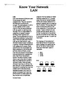
Administration
Admin Department has 10 hosts in its network. The Admin department has the Network address 192.168.10.32 up to 192.168.10.63, so it can be 32 hosts in the network but among them 1 bit will be use for network address and 1 bit will be used for the broadcast address. So the remaining 30 network address within this network can be assign to the hosts in the network.
Like the above diagram all the departments have this kind if IP addresses and the host addresses.
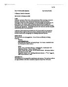
Training Dept 1 Training Dept 2
The iTekx company has the two training department called Training department 1 and training department 2, T1 is having 14 host in its network and T2 has 12 hosts in its network.
MMC R’n’D
On the first floor of the iTekx company there are two departments called MMC and R’n’D department having 16 and 24 hosts in each department.
`
The above diagram shows the basic network diagram of the Administration department, training department 1 and the training department 2. The network address are given to the each host of the network. All the host are connected to the switch via Ethernet. The network address is also given too the switches are 192,168.10.33 (Admin Dept), 192.168.10.65 (Training 1), 192.168.10.96 (Training 2), 192.168.10.129 (MMC), 192.168.10.161(R’n’D). This network connection enables the host of each department to connect the other host of the same department.
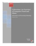
As we have already assign the Network address to all the hosts of the each departments. We need to assign the network address to each switch of the departments.
After establish the network within the different departments, we need to establish the connection between the all the departments because may the information of the different department can be used by the another departments. All the switches of the different department the connected to the one router. The network address is given to the router as well. This mechanism allows all the department to interact with each other and perform file transfer operations. When the packets comes to an router, the frame header and trailer are stripped off and the packet located in the frame’s payload field is passed to the routing software. The routing software will not see the packet address. It will just see the IP address of the packet and perform the transmission of the data.
Discussion of the suitable physical media and network devices
Firstly, after defining and IP addresses and the network addresses we need to do establish the network connection between the host of the same network and host of the different network. First of all we need to establish the cabling between the all the hosts in the same network of the one department.
Cabling
First of all the infrastructure of the office building is 100 meters in height and 130 meter in wide. So for that some options are there for the cabling. We can use fiber optic cable, coaxial cable, or fast Ethernet. I prefer to use fast Ethernet with the proper connector in my network design. There are two option in the fast Ethernet 10baseT and 100baseTX they both can be use for the 100meter long small office in fracture.
The cables and connectors specifications used to support Ethernet are derived from the electronic industries associations and the newer telecommunications industry association (EIA/TIA) standard body. The categories of cabling defined for Ethernet are derived from the EIA/TIA-568 commercial building telecommunications wiring standards. The EIA/TIA specifies a RJ45 connector for unshielded twisted pair (UTP) cables. The word RJ specifies registered jack and the number 45 refers to a specific wiring sequence.
Ethernet is a large, diverse family of frame-based computer networking technologies that operates at many speeds for the Local area networks (LANs). It can defines a number of wiring and signaling standards for the physical layer, through means of network access at the media access control (MAC) and data link layer, and a common addressing format. The Ethernet has been standardized as IEEE 802.3. The combination of the twisted pair version of the Ethernet for connecting end system to the network with the fiber optic versions for site backbones become the most widespread wired LAN technology in use which is in used from 1990.
A fast Ethernet is a collective term for a number of Ethernet standard that carry traffic at the nominal rate of 100 MBit/sec, against the original original Ethernet speed of 10 MBit/sec. of the 100 Mbit Ethernet standards 100baseTX is by far the most common and is support by the vast majority of the Ethernet hardware currently produced.
Switch
The network switch or switch is a networking that performs the connection of multiple network segments with forwarding based on MAC addresses at up to the speed of the hardware. A switches can connect at 10,100 or 1000 Megabit/sec at half or full duplex. A switches can connect Ethernet, token ring, fiber optic, or any other types of the packet switched network segments together to form an internetwork.
Switches are similar to the bridges, many people uses the term interchangeably. The switch is most often used to connect individual computers. Suppose from the figure host A wants to send the file to host, the switch are most actively forward the frame from A to B because there is no other way for the frame to get there. One another advantage to using the frame is, each port is its own collision domain, and switches never lose frames to collisions. However, if frames come in faster then they can be transmitted, the switch may run out of buffer space and have to start discarding the frames.
Router
Routers are the physical network device that can join multiple either wired or the wireless network together. Or we can say the wired or wireless network router is a layer 3 gateway, that means it connects the networks and the routers operates at the network layer of the OSI model. In the another definition a router is a computer network device that buffers and forwards data packets across the internetwork towards their destinations, this process is called routing.
When a packets comes into the router, the frame header and trailer are stripped off and the packet located in the frame’s payload field is passed through the routing process. The application gateway understands the format and contents of the data and translate message from one format to another.
Discussion and critical analysis of the chosen security measure.
I have used the fire wall systems to protect my network from outside network threats. A network firewall is a system or the group of the system used to control the access between the two networks normally it is called trusted network and the untrusted network using the filters. It can be composed of the one single router, multiple routers, or may be multiple host systems. After implementing the network firewalls it controls the access of both networks. It can be configured to keep unauthorized or outside users from gaining access of the internal network.
Many firewalls can be applied within an organization to control the unauthorized access between the different departments. There are some applications where we can use firewalls to prevent the network.
User authentication: - firewall can be applied to require user authentication. This functionality allows network administrator to control the access of the unauthorized users to access some specific files and companies recourses.
With the using some of the firewall functions we can even hide some private and important network from the untrusted networks.
Basically the firewall has two packet filtering router that do the to packet filtering. The advantages of this mechanism are that every incoming packet must transits two filters and one application gateway to go in or out.
Conclusion and further work:
The network design which I have used in my coursework, I think it is the quality solution of the given application of the iTekx company Plc. Firstly I have thought it is a small company, and the design of the network is smaller too. There are mainly five departments each department is having minimum of 10 and maximum of 24 computers or hosts. I have use the quality of equipments which are really cheaper then other costly available networking devices. This can be very easily efforts by the small company like iTekx Company Plc.
In the conclusion of my coursework I feel that the network part like subnetting, routing, cabling, switching, which is represented in the diagrams are the good solution for the iTekx company Plc with the proper security solutions. But I can implement more security on this network bye using NAT technology. Which are mostly used by the private networks to prevent the unauthorized access and internet threats.
Reference and supporting materials
I have used merely two books to understand the concepts and the definitions of the network and the network devices. These books are
- Interconnecting Cisco Network Devices – CISCO Systems
- Computer Networks – Andrew S. Tanenbaum
Even I have got some useful information from the internet websites too. These websites are.
Introduction:-
The iTekx company Plc has mainly five departments with the number of Computers. The company has two floors with 100 meters in height and 130 meter of weight. The administration department is the main remote department, and the other departments are Training 1 and 2, multimedia centre and R’n’D department.