To investigate what would be the most ideal loads to put onto the end of the wire I knew that I will take measurements every 0.5mm therefore I have a resolution of 0.5mm. I therefore have to ensure that the length should be such that strain at the elastic limit is several times the 0.5mm so that I will get consistent results.
To ensure that the extension is measured as accurately as possible I will take multiple readings and take the mean of them as an average value. This will maximise accuracy.
The sample wire then runs from the clamping area along the desk to the other side of desk where it runs through a pulley. The purpose of using the pulley is so horizontal measurement of the sample can be accomplished. This method of measuring the extension of the wire would be much better than measuring it vertically because it would allow a longer sample to be tested therefore allowing us to use bigger numbers, making the data handling and presenting a lot easier. It will also ensure that the distance that the stress is applied over constant. The pulley has to be smooth; hence it is made from plastic. It needs to be smooth so that there is little friction because this would add an uncertainty to the results.
The method used for measuring the extension of the wire is a measuring stick and marker on the sample. We can then use the marker on the sample along with the measuring stick to measure how far it moves with each weight added.
The weights will be added at the pulley end of the sample. I will hang a hook weight holder on a carefully tied loop at the end of the sample and therefore I will be able to add weights to the end of the sample and measure the extension for each weight.
I will have to measure the original length of the wire before I add any weight and I will also have to use a micrometer to measure the diameter of the wire so that I can then work out the area to use in the calculations that I want to make.
Once I have collected my results I will be able to work out from the weight added how much force there was on the wire, I will then have the extension, original length, the area and the force. With these values I can work out the stress and the strain and therefore plot this on a graph and calculated young’s modulus and study the graphs.
I knew that I should plot these graphs because stress takes into account areas and strain takes into account lengths, therefore it would make sense to plot this graph as opposed to a mass extension graph or similar.
I will collect the results and then add them into a database to make calculations and plot the stress strain graphs.
I will also measure the diameter of the wire so that I can then calculate the area of the wire. To measure the diameter I used a micrometer.
These were my results….
RESULTS
Below are the results that I collected.
Area of sample =
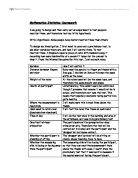
The formulae that I needed to use for these calculations were as follows…
Area is equal to diameter divided by 2, squared and multiplied by TT.
Stress is equal to force divided by area.
Strain is equal to extension divided by original length.
I used scientific notation for the calculations, scales and data sheets because they allow smaller and larger numbers to be represented on a more concise scale and prevent the long numbers that are hard to visually understand and compare, let alone plot.
After calculating the stress and strain I plotted them on a Stress Strain graph. I used a stress strain graph because I know that Young’s Modulus will be represented by the gradient of the line and I also know that stress takes into account area and strain takes into account length.
RESULTS
ANALYSIS
This line graph of stress vs. strain shows both the elastic and a plastic region.
We can tell that the elastic limit of the copper wire was at 88MPa from the point on the graph where the straight line ends and the curve begins to start. This is the yield stress of the copper wire.
After this point the material becomes plastic. This point is shown on the section of the graph taken and shown on the right. The Copper becomes plastic as stress increases after beginning in the elastic region shown on the graph.
The plastic behaviour of the material is due to the dislocations in the poly crystalline structure of the metal moving. These dislocations or gaps in the structure can move along by process of slip. As more and more of the dislocations move and form a tighter crystalline structure then the material will become more brittle. Once the dislocations have been moved they cannot be moved back. This is what happens in plastic behaviour.
The gradient of the line on the elastic area of the graph was 28 GPa. This is the young’s Modulus for Copper that I have found.
The last point on the graph may well be incorrect because we did not actually have chance to take any measurements before the material broke. I think that it is due to a mis-recording that we have this value and in actual fact it should not be included on the graph. Otherwise, the graph follows the characteristic pattern of a stress vs. strain graph, starting off with an elastic region and then moving into the plastic region, with the modulus reducing with strain and then slight increases before it yields.
The theory behind the tensile properties of the copper can be traced back to the particle theories within the sample. All the atoms are in a crystalline arrangement and during the elastic area they are stretched and elongated until they reach their elastic limit when they will begin to slip against each other and permanently deform.
As the wire extends the crystalline structure stretches and begins to dislocate and the dislocations slip until the structure is perfect and there are no dislocations left. This is called slip.
The elastic region of the graph, when presented individually, shows that the results are not actually very accurate. To investigate the actual accuracy of my results I used standard deviation. I worked at a root mean square error. I worked out all the errors between the measured points and the straight line fits and then squared them. After this I added them together and divided by the number of values I had added together to find the mean and then square root this. This gives me the RMS error which is the standard deviation.
Total = 635 Divide by 9=
Standard deviation = 8.40
Having worked out the standard deviation of the stress I can divide this by the gradient to get the standard deviation of the strain. This is equal to 8.40 / 28 = 0.3mm
This could be due to a number of reasons. There is lots of scatter between the points therefore they are not very repeatable. I think that this could be due to the fact that we measured the extension of the wire in mm. This unit of measurement is not accurate enough therefore the resolution is not good. This is because it was too difficult to measure accurately to 1mm with a metre rule. Measuring the extension of a wire in mm is hard when you have a mm scale. This may well be the cause of any inaccuracies.
Other possible causes of these inaccuracies could be friction in the pulley. Any friction could prevent the smooth movement of the wire, causing it to settle and then jump to overcome the friction. By recording without the pulley, and hanging the weights from the wire in a vertical position this would eliminate any possibility of friction on the pulley affecting the results.
To improve the experiment we could use a longer length of wire so that it would be easier to measure the strain, for example, if we used a sample ten metres long we would have a ten times better resolution, making our results much more manageable. We would then need to ensure that the weight of the 10M wire was very much smaller that the weight we added to induce strain.
We could also have used a more accurate measuring device to make our results more accurate. One example of this would be to use a vernier scale. This would increase accuracy of measurements meaning that our results would overall be more accurate.
The plastic region of the graph generally follows the expected pattern for a stress strain graph. The only strange result is the last point which is probably anomalous. Reasons for this were discussed earlier.
There is a very large plastic region for this material; in fact the material has stretched by nearly ten percent before breaking.
If I was to conduct the experiment again I would take steps to increase the accuracy of my results. These steps would include more repeats, trying the test without a pulley to eliminate risk of friction, and using a longer sample to make the results a little bit more manageable. I would also use a vernier scale to record my results.
CONCLUSIONS
From my experiment I can conclude the following…
The yield stress for copper sample was 88MPa
The breaking point for the copper sample was at 250mm with a force of 8.5 N acting on the sample.
The Young’s Modulus for the copper sample was 28 GPa
The copper sample stretched almost 10% of its original length.
The evidence for all of the above statements has been graphically presented and the conclusions were brought about by analysis of the graphics.
I have discussed problems, causes and improvements that could be made to my experiment but overall I am happy that I have sufficient evidence to support these statements.