A capacitance meter.
Extracts from this document...
Introduction
THE CAPACITANCE METER
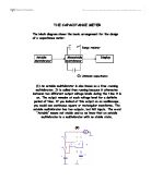
The block diagram shows the basic arrangement for the design of a capacitance meter.
Range resistor
Astable Monostable Display 


Multivibrator Multivibrator
Cx Unknown capacitance
(1) An astable multivibrator is also known as a free-running multivibrator. It is called free running because it alternates between two different output voltage levels during the time it is on. The output remains at each voltage level for a definite period of time. If you looked at this output on an oscilloscope, you would see continuous square or rectangular waveforms. The astable multivibrator has two outputs, but NO inputs. The word “Astable” means not stable and so we know that an astable multivibrator is a multivibrator with no stable state.
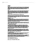
(2)
The circuit diagram for the astable multivibrator using IC 555 is shown here. The astable multivibrator generates a square wave, the period of which is determined by the circuit external to IC 555. The astable multivibrator does not require any external trigger to change the state of the output, hence the name free running oscillator.
Middle
(6) The preferred value for R1 is 12kΩ and the preferred value for R2 is 1.5kΩ.
(7) The monostable multivibrator (sometimes called a one-shot mulitivibrator) is a square- or rectangular-wave generator with just one stable condition. With no input signal (quiescent condition) one amplifier conducts and the other is in cutoff. The monostable multivibrator is basically used for pulse stretching. It is used in computer logic systems and communication navigation equipment.
The operation of the monostable multivibrator is relatively simple. The input is triggered with a pulse of voltage. The output changes from one voltage level to a different voltage level. The output remains at this new voltage level for a definite period of time. Then the circuit automatically reverts to its original condition and remains that way until another trigger pulse is applied to the input. The monostable multivibrator actually takes this series of input triggers and converts them to uniform square pulses. All of the square output pulses are of the same amplitude and time duration.
(8)
Monostable multivibrator often called a one shot
Conclusion

To calculate Rs I will use OHMS law.
Rs=V/I
Rs=9/0.0125
Rs=720Ω
(13) The zener fails to regulate when the current through it drops to 0. the current through Rs will then be 2.5mA.
a)VRs=2.5mA*Rs
VRs=2.5mA*720Ω
VRs=1800
b) The minimum voltage the battery can drop to and still provide 5V across the capacitance meter circuit is 5V.
c) Rs=VRS/2.5mA
Rs=1800/2.5
Rs=720
(14) This is the pin out diagram for the TO92 type regulator.
(15)
R=V/I
R=2/0.005
R=400Ω
This student written piece of work is one of many that can be found in our AS and A Level Electrical & Thermal Physics section.
Found what you're looking for?
- Start learning 29% faster today
- 150,000+ documents available
- Just £6.99 a month