Precautions:
- When swirling the rubber bung, care should be taken not to let the rubber bung hit anyone nearby.
- The angular speed when swirling the rubber bung should be kept constant.
- As the presence of wind would add air resistance to the swirling motion, which in turn increase the error in time-taking, the experiment should be carried out in a static environment with little disturbance.
- The one who swirl the rubber bung should be the same person throughout the experiment for the sake of minimizing the error in time-taking of this experiment. The one who manipulate the stop watch should be the same person for the same reason.
- The glass tube should be held vertically to ensure an angular speed of constancy.
- While keeping a constant angular speed of the rubber bung, the one who swirl it should not have the feeling of adding much force swirl the bung. He should have the feeling that only adding very little force is needed to keep the rubber bung in motion, or otherwise the rubber bung is actually not in a constant angular speed.
Data and data analysis:
Mass of the rubber bung (m) = 0.0211kg ± 0.00005kg
Length of the nylon thread (l) = 0.800m ± 0.0005m
Take g = 9.81ms-2
With M = 0.15kg,
Absolute difference between W and T = 1.52 – 1.4715 = 0.0485N
Percentage difference between W and T = 0.0485/1.4715 x 100% ≈ 3.30%
With M = 0.20kg,
Absolute difference between W and T = 1.9620 – 1.96 = 0.0020N
Percentage difference between W and T = 0.0020/1.9620 x 100% ≈ 0.102%
With M = 0.25kg,
Absolute difference between W and T = 2.4525 – 2.19 = 0.2625N
Percentage difference between W and T = 0.2625/2.4525 x 100% ≈ 10.7%
With M = 0.30kg,
Absolute difference between W and T = 2.9430 – 2.63 = 0.3130N
Percentage difference between W and T = 0.3130/2.9430 x 100% ≈ 10.6%
With M = 0.35kg,
Absolute difference between W and T = 3.4335 – 3.12 = 0.3135N
Percentage difference between W and T = 0.3135/3.4335 x 100% ≈ 9.13%
Error Analysis:
Percentage error in mass of the rubber bung (m) = 0.00005/0.0211 x 100% ≈ 0.237%
Percentage error in length of the nylon thread (l) = 0.0005/0.800 x 100% ≈ 0.0625%
Sources of error
- As there was air resistance present to oppose the swirling motion of the rubber bung, this lowers the accuracy of the experiment.
- As the rubber bung was swirled at a fast speed, it was hard for the observer to determine whether the bung has completed a revolution. Besides, the observer had his reaction time involved in time-taking. All these have contributed to the error in the time recorded.
- As friction exist between the string and the upper mouth of the glass mouth, it caused energy loss from the swirling motion of the rubber bung. This causes error in the circular motion of the rubber bung and hence the time recorded.
- As the time was recorded for 30 complete revolutions, which was quite a long time, the one who swirled the rubber bung might not be able to keep the angular speed of the bung constant. This lowered the accuracy of the experiment.
- It was very formidable for the rubber bung to swirl in a purely horizontal plane. Even if it could, during the 30 revolutions, the motion of the rubber bung might alter and not be swirled in a horizontal plane for some revolutions.
Improvement
- A rubber bung of larger mass but same size can be used so that the effect of air resistance can be reduced.
- A time-scaler or a stroboscopic lamp can be used to observe and record the motion of the rubber bung instead of a human observer. It can increase the accuracy in time-recording.
- Lubricants such as oil and Vaseline can be smeared at the upper mouth of the glass tube so that the friction between the string and the upper mouth of the glass mouth can be reduced.
- It can be amended that time is recorded for every 10 oscillations. This can reduce the chances for the one who swirled the rubber bung to have the angular speed of the rubber bung altered during the time-taking period.
- A mirror can be placed in front of the one who swirled the rubber bung to see whether the rubber bung is swirled in a horizontal plane and he can be conscious about any changes of the motion of the rubber bung.
Discussion
From the results obtained, it can be easily seen that the differences between the tension of the string and the centripetal force of the circular motion of the rubber bung are 3.30%, 0.102%, 10.7%, 10.6% and 9.13%, with varying mass(M) and hence tension(T) used. It actually does not show much difference between the two values. The errors are indeed caused by the matters stated in ‘Sources of error’. Consequently, it can be concluded that the tension (T) of the string is approximately the same as the weight (W) used.
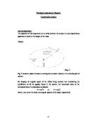
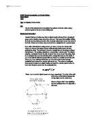
Furthermore, we cannot circle the rubber bung exactly in a horizontal plane. As shown in Fig.3, if the rubber bung is circled in a horizontal plane, the tension (T) of the string will no longer contribute a vertical force component to balance the weight (W) of the rubber bung. Hence, there will not be any force to balance the weight of the rubber bung. Consequently, the rubber bung must make an angle θ, which is more than or less than 90o, with the vertical, and thus the rubber bung cannot circle in a horizontal plane.
Conclusion
From the experiment, as the tension (T) of the string is approximately the same as the weight (W) used, it can be verified that the tension in a centripetal force apparatus is equal to the weight of the mass.