Diode Application in Rectifier Circuits
![Authors Avatar]() by
tan9797tangmailcom (student)
by
tan9797tangmailcom (student)
ELECTRICAL ENGINERING
LABORATORY 1
EEE230
EXPERIMENT 5
DIODE APPLICATION
________________
CONTENTS
Title
Page
Introduction/theory
PART A:3-4
PART B:9-10
Result
PART A:5-6
PART B:11-13
Discussion/Question
PART A:7-8
PART B:14
Conclusion
15
References
16
________________
PART A ; Rectifier circuit using diode
Introduction
In this experiment, we have learned about the applications of diode. First, we were revising the basic of equipments handling. Secondly. we were knew that one of the main component used in the making of rectifier circuits are diodes and there are three types of rectifier circuits Thirdly, we have been introduced to the function of a capacitor in a rectifier circuit. Lastly, we also have learned about how to build a simple diode clipping and diode clamping circuits
Theory
Usually we have three main type of rectifier it is a half-wave rectifier circuit, center tap full-wave rectifier circuit and full-wave bridge rectifier circuit.
Firstly about half-wave rectifier circuit, when diode was connect to source AC voltage supply, it will be alternately forward-biased, and then reverse-biased, during each cycle of the AC sine-wave. When a single diode is used in a rectifier circuit, current will flow through the circuit only during one-half of the input voltage cycle like in figure below. For this reason, this rectifier circuit is called a half-wave rectifier. The output of a half-wave rectifier circuit is pulsating DC.
http://nuclearpowertraining.tpub.com/h1011v1/img/h1011v1_104_1.jpg
Second is about center tap full-wave rectifier circuit is uses two diodes connected to the secondary of a center tapped transformer. The AC on each side of the center-tap is ½ of the total secondary voltage. Only one diode will be biased on at a time the prose to be center tap full-wave rectifier is like below.
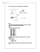
Last is about full-wave bridge rectifier circuit, The Bridge is shown in the figure below. The circuit has four diodes connected to form a bridge. The ac input voltage is applied to the diagonally opposite ends of the bridge. The load resistance is connected between the other two ends of the bridge.
http://www.visionics.ee/curriculum/Experiments/Bridge%20Rectifier/Images/Image79.gif
________________
RESULT PART A
Experiment 5.1
Without capacitor With capacitor
Experiment 5.2
Without capacitor With capacitor
Experiment 5.3
Without capacitor with capacitor
Input
Output
dc output voltage
(without capacitor)
Ripple voltage
(with capacitor)
Half-wave rectifier
6.60V
0.80V
Center tap full-wave rectifier
5.56V
0.38V
Full-wave bridge rectifier
5.52V
o.43V
________________
DISCUSSION
Based on the experiment above, on the first positive half cycle the diode conducts charging the capacitor left. This is on the right end, the right end of the capacitor with respect to the ground. It ...
This is a preview of the whole essay
Experiment 5.2
Without capacitor With capacitor
Experiment 5.3
Without capacitor with capacitor
Input
Output
dc output voltage
(without capacitor)
Ripple voltage
(with capacitor)
Half-wave rectifier
6.60V
0.80V
Center tap full-wave rectifier
5.56V
0.38V
Full-wave bridge rectifier
5.52V
o.43V
________________
DISCUSSION
Based on the experiment above, on the first positive half cycle the diode conducts charging the capacitor left. This is on the right end, the right end of the capacitor with respect to the ground. It is also has an AC peak sine wave coupled across it from source to node. The sum of the two is a peak sine riding on a negative DC level. The diode only conducts on successive positive excursions of source V if the peak exceeds the charge on the capacitor. This only happens if the charge on the capacitor drained off due to a load. The charge on the capacitor is equal to positive peak of V. The AC riding on the negative end, right end, is shifted down. The positive peak of the wave form is clamped to 0V because the diode conducts on the positive peak.
In the negative cycle of the input AC signal, the diode is forward biased and conducts, charging the capacitor to the peak positive value. During the positive cycle, the diode is reverse biased and thus does not conduct. The output voltage is therefore equal to the voltage stored in the capacitor plus the input voltage gain.
In the positive cycle of the input AC signal, the diode is forward biased and conducts, charging the capacitor to the peak voltage value. During the negative cycle, the diode is reverse biased and thus does not conduct. The output voltage is therefore equal to the voltage stored in the capacitor plus the input voltage gain, so Vout = negative.
A positive biased voltage clamp is identical to an equivalent but with output voltage offset by the bias amount. A negative biased voltage clamp but with the output voltage offset in the negative direction by the bias amount.
PART B:Diode clipping and clamping circuit.
Theory
Diode characteristics
From the figure above we can see the diode has a terminal not like the transistor. The negative (-ve) terminal is know as cathode and for positive (+ve) terminal is know as anode.
Diode in electrical is a component just allow electricity flow in one direction from anode to cathode. The diode can become conductor went the diode are place in forward bias and also become insulator if place in reverse bias.
Like the figure (a) the diode become a conductor because went diode in forward bias the resistance in diode become lower and in figure (b) the diode became higher resistance because of that the current cannot through it.
Diode clipping circuit
A clipping circuit consists of linear elements like resistors and non-linear elements like junction diodes or transistors, but it does not contain energy-storage elements like capacitors. This clipping function is to cut the upper or the lower portion of signal this figure below is example the circuit for diode clipping circuit.
Diode clamping circuit
The clamping circuit is difference with the clipping circuit, because the clamping circuit are build is to clamp to a required DC level, basically the circuit of clamping is the load was parallel with diode like in figure below.
RESULT PART B
PART 1
Waveform Result for Figure 5.7
Waveform Result for Figure 5.8
Waveform Result for Figure 5.9
Waveform Result for Figure 5.1
PART 2
________________
DISCUSSION
Part 1 Clipping Circuit : Principles of operation
The schematic of a clamper reveals that it is a relatively simple device. The two components creating the clamping effect are a capacitor, followed by a diode in parallel with the load. The clamper circuit relies on a change in the capacitor’s time constant; this is the result of the diode changing current path with the changing input voltage. The magnitude of R and C are chosen so that \scriptstyle \tau = RC is large enough to ensure that the voltage across the capacitor does not discharge significantly during the diode's "Non conducting" interval. During the first negative phase of the AC input voltage, the capacitor in the positive clamper charges rapidly. As Vin becomes positive, the capacitor serves as a voltage double; since it has stored the equivalent of Vin during the negative cycle, it provides nearly that voltage during the positive cycle; this essentially doubles the voltage seen by the load. As Vin becomes negative, the capacitor acts as a battery of the same voltage of Vin. The voltage source and the capacitor counteract each other, resulting in a net voltage of zero as seen by the load
Part 2 Clamping circuit : Basic operation
The schematic of a clamper reveals that it is a relatively simple device. The two components creating the clamping effect are a capacitor, followed by a diode in parallel with the load. The clamper circuit relies on a change in the capacitor’s time constant; this is the result of the diode changing current path with the changing input voltage. The magnitude of R and C are chosen so that \scriptstyle \tau = RC is large enough to ensure that the voltage across the capacitor does not discharge significantly during the diode's "Non conducting" interval. During the first negative phase of the AC input voltage, the capacitor in the positive clamper charges rapidly. As Vin becomes positive, the capacitor serves as a voltage double; since it has stored the equivalent of Vin during the negative cycle, it provides nearly that voltage during the positive cycle; this essentially doubles the voltage seen by the load. As Vin becomes negative, the capacitor acts as a battery of the same voltage of Vin. The voltage source and the capacitor counteract each other, resulting in a net voltage of zero as seen by the load.
CONCLUSION
part A
From that experiment we can conclude the diode can change the AC input to the DC output. Because the diode just allows current flow to it just in one direction only. How we know in this experiment we find many type of rectifier such as half-wave rectifier circuit like in figure 5.1, center tap full-wave rectifier circuit like in figure 5.2 and full-wave bride rectifier like in figure 5.3, every circuit are given the different type of output voltage supply and different type of output wave form and this experiment we also get how to use oscilloscope and multimeter better. This experiment we also know with is the best rectifier. And the best rectifier is full-wave rectifier.
Part B
From both experiment we can conclude the diode can become insulator when in reverse biased and also can be a conductor when in forward biased because that’s time the resistance become low and can make the current easily flow trough diode. In this experiment also we know the how to differentiate the clipping circuit and clamping circuit just look at the circuit for example the clipping circuit the load is in series with the diode and the clamping circuit is the load is parallel with the diode. This experiment we know the clipping and clamping circuit are function to cut the signals peak.
________________
REFERENCE
Internet
* http://sleepycity.net/troublemakers/diodehttp:
* http://www.electronickitsbychaneyelectronics.com
* http://penang.i-learn.uitm.edu.my
* http://www.scribd.com/
* http://nuclearpowertraining.tpub.com/
* http://metroamp.com/wiki/
* http://www.allaboutcircuits.com
Books
* Laboratory manual
* Fundamentals of electric circuit