After carrying out this experiment I also decided to use an ammeter which was a 0 to 10amp ammeter which displays the amps to 2 d.p. I felt an error from the ammeter of (for example) during the 1V to 2V reading was only 5% (to 0 d.p). The working for this is shown below.
(2V Reading) - (1V Reading) = Difference
=> 0.89 - 0.70 = 0.19
Error = + or – 0.005 on each reading.
Therefore: error on two readings could be 0.01
% Error = Numerical Error x 100
Difference
=> Error = 0.01 x 100 = 5.26
0.19
The voltmeter I plan to use is a 0 to 15V meter that displays to 2d.p, as this was even more accurate with an error of 0.5% between each reading. Both these accuracy’s were acceptable for my experiment.
Method
- Set up the apparatus as shown in the circuit diagram above (plugging the wires into the two 12V D.C. terminals at the back of the power pack).
- Using the rheostat record the current from 1V to 12V, in 1V intervals.
- Do steps 1 to 2 three times and record the average of these repetitions. This will help to cancel out the effect of any possible anomaly.
-
Use the formula P=VI to calculate the power dissipated by the filament (for these averages).
There are few safety precautions which need to be taken when carrying out this experiment. However one precaution is to make sure the power pack is turned off at the socket before changing anything in the circuit.
The test will be a fair test as the only change in the experiment from one voltage to the next will be me moving the rheostat (every test will use exactly the same equipment).
Hypothesis
If the light bulb were ’’Ohmic’’ I would expect the following results:
Because (if it were Ohmic) : V=IR
and : P=VI
than: P=V x V
R
and therefore: P=V2
R
This implies that P is proportional to V2 and a graph of the results would look like:
P
V2
However the filament of the light bulb will not obey ohm’s law as it loses energy as heat as well as light. As the filament heats up, the molecules and electrons in the wire gain more kinetic energy and move about faster. As they move about faster, they collide more often with electrons and molecules, inhibiting the movement of some of the electrons through the wire. This then results in resistance going up, meaning that less power is dissapated from the bulb.
This means that P will now be proportional to Vn (where ‘’n’’ is a certain number). This number will have to be lower than 2,as energy is being lost. With this in mind, I will go half way between 1 and 2, and predict that P is proportional to V1.5.
Results
I then took the mean average of all the results to lessen the effect that anomalies might have and calculated power using the formula P=VI (the values are rounded to 2 d.p).
I then plotted these results on a graph, which is shown on the next page.
Analysis and Conclusion
To check whether my hypothesis was right I processed these results further, by making graphs of P against Vn where 1<‘n’<2 at 0.1 intervals. When I found a graph that looked the straightest, I stopped. These graphs and results are shown below and on the following pages.
Voltages to the power ‘n’
After looking at the V1.5 graph I thought it looked pretty straight, but to make sure the V1.6 was not straighter, I plotted that as well. After plotting this I was still not 100% sure, so I plotted V1.7 to make sure I was right.
I then made full-page graphs of V1.5 and V1.6 to see which was straighter, and therefore closer to the answer. These are shown on the next page.
After analysing these two graphs I decided that V1.5 graph was straighter. But there is also another of checking my hypothesis. I could do this mathematically by using logarithms.
If : P ∝ Vn
=> P = KVn (K=constant)
Than : ln P = ln K + ln (Vn)
Knowing that ‘’ln (Vn) = n ln V’’ allows me to substitute in to get:
ln P = ln K + n ln V
=> n = ln P – (ln K)
ln V
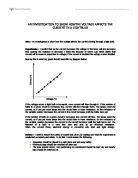
This equation than allows me to calculate ’K’ when I have ‘n’. To find ‘n’ I will plot ‘ln P’ against ‘ln P’, and ‘n’ will be the gradient. This is shown below.
I found the gradient of this line to be roughly 1.45 to 2 d.p. and therefore;
n = 1.45
This then allows me to calculate ‘K’, by substituting values into the formula above (in this case the values for 5V).
n = ln P – (ln K)
ln V
=> 1.45 = 1.909543 – (ln K)
1.609438
and ∴ ln K = 1.909543 – (1.45 x 1.609438)
=> ln K = - 0.4241421
and ∴ K = 0.65 to 2 d.p
To conclude, after using natural logarithms to check my original hypothesis I found that the following formula was true:
P = 0.65V1.45
And I can say that these results (to 1 d.p) support my original prediction that the value was of n was 1.5.