To take the voltage of an object, the shunting resistor must be placed in series, as the resistance of the moving-coil galvanometer is not very high.
Some formulae which may be useful during this experiment is:
Method
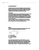
The experiment firstly started by looking at calculating the resistance of the voltmeter. This was done by setting the circuit up as below:
E = d.c. power supply
M = Voltmeter being tested
Rm = Voltmeter resistance
I = Current
The avometer was then placed upon successive ranges of 3v, 10v, 30v, followed by the digital voltmeter on ranges 1v and 10v. Following this the current on the dc control supply was turned fully clockwise and the voltage supply fully anti-clockwise, in doing so the voltmeter was adjusted to one of the above ranges. R was then made to equal zero, and this made the voltmeter ready to measure E. The voltage was then increased to the upper end of the range, to give the value E. The resistance, R was adjusted till the voltmeter reading, Vm fell to E/2. The value for Rm was then compared to other values for voltmeter’s and different ranges.
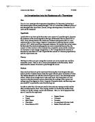
E = d.c. power supply
A = Ammeter being tested
Rm = Voltmeter resistance
I = Current
Following this the ammeter resistance was investigated. The avometer was adjusted to the 300μA range, and the voltage supply knob was turned fully anticlockwise. The supply was then turned on and E was increased to 1v, which was measured by the digital voltmeter. The current I was recorded and compared to the expected value of 100μA. Then using the following formula,, Ra was calculated, and then the experiment was repeated with E=0.1v, range 50μ A and 10v, range 1mA.
Results
These results were taken using the avometer, and the intention was to find Rm, from the results.
These results were taken using the digital voltmeter, and the formula was used because the E/2 was not reached.
These results were taken using the avometer, and with the intention of finding Ra.
Discussion
The results from the digital voltmeter suggest that there is very little amount of difference in resistance needed to reduce the emf by half.
The resistance of the ammeter decreases as the range is increased. This is because when you change the range you're changing the shunt resistance. On the other hand the resistance of the voltmeter increases as the range is increased.
The voltmeter is rather high in resistance and therefore only needs a small current travels through the meter itself. It is used in parallel, meaning that it is not the only path for the current. The ammeter is placed in series and must therefore provide a path for the entire current. It would be difficult to develop a meter that would handle significant amounts of current. This means the ammeter uses a shunt to allow some of the current to travel through a course parallel to the meter. If the shunt malfunctions, it is likely the meter will not be able to handle the current.
When using the digital voltmeter it has an error of ±1 digit. Whereas the avometer is a moving needle, which means the error is much greater as the needle can seem in two different positions from different angles.
Conclusion
In conclusion it was found that the resistances for both the ammeter and voltmeter behave differently, with the ammeter decreasing as the range is increased and the voltmeter increasing with range.