Current (I)
So when the resistance goes up the current goes down and when the resistance goes down the current goes up. The voltage should stay the same as it is the same power pack on the same setting so the voltage should not change.
To measure the current I would put the ammeter in series with the LDR and with a 9V power pack. Then I would record the results from different light intensities.
If another resistor is put into the circuit in series to the LDR then a potential divider can be made this should give a better reading than the resistance alone.
A potential divider works by allowing a different voltage to be tapped off in between the two resistors. This is because the voltage doesn’t stay the same all the way round the circuit. As the electrons go round the circuit they lose voltage, by the time they reach the other side of the battery they are at 0 volts.
In the potential divider circuit the voltage difference can be measured if the volt meter is around the fixed second resistor (R2) then as the LDR goes up in resistance the reading on the meter should go down as the LDR would “use up” the voltage.
To get the greatest voltage difference the fixed resistor (R2) should be the same resistance as the average of the LDR so half way between it highest and lowest reading. If it’s set up exactly right it should read half the supply voltage.
Obviously to get a reading I need to have a light source. For this I wam going to use a LED (light emitting diode). I coul use this directly on to the LDR, however if I reflect the light off of a piece of white plastic. Then for every 5 cm I move the plastic the light would have to travel an extra 10 cm. So when it is moved it should make more of a difference to the resistance.
I will make this piece of equipment to do the experiment.
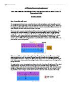
I used a black pipe as black doesn’t reflect light, it absorbs it. So any light that shines onto the LDR has to have been reflected off of the white disk.
It will be arranged in this circuit;
I can estimate the v out if I know the resistance of the LDR and the fixed resistor. I can do this by using this formula;
V out = original voltage x R2
R2 + R1
Method for experiment one
This is the first bit of the investigation; I need to find out what the resistance is of the LDR at different distances from the white disk. To do this I will follow these next few simple steps.
- Mark every 5cm on the pole that pulls the disk into place.
- Connect the LDR directly up to the multi meter and set to ohms.
- Connect the LED up to a 9 volt DC power source with a resistor in series to protect the LED.
- Move the rod to 0 and record the reading off of the multi meter.
- Do this at 5cm intervals until you reach 50cm.
Results
On the next page I have done a graph it is to show these results. I have put a line of best fit on it and most of the points are not far off that line so it looks as though it was fairly accurate. It shows what I already knew that as you move the white disk away the light intensity will decrease as it has to travel further, I know this because the resistance goes up as the light intensity goes down.
Now I have these results I can estimate the results to the next experiment. I also know that I need about a 1.5MΩ for the fixed resistor.
Prediction for second experiment
Using the formula that I wrote earlier I can now work out the v out simply by substituting the figures in.
I would expect the values to be around these however not exactly as these are theoretical values and they don’t take in to account the resistance of the wire, heat changing the resistance of any thing, electrical noise which also means the circuit is in efficient and loses energy, and that is assuming the voltmeter has an infinite resistance, however in practise the voltmeter can not have an infinite resistance as then it wouldn’t be able to conduct and it would not get a reading. It is also difficult to control the other things I have mentioned.
I would also expect the general shape of the graph to be the same only with out the problem with the 0cm point a bit out.
Method for second test
This is very similar to the first as the only difference is that you get rid of the multi meter and add a circuit in where the LDR is connected to a 1.5MΩ fixed resistor in series and the fixed resistor has a voltmeter connected to it in parallel. This circuit should be powered by a separate 9 volt DC power supply. Then its just a case of taking the results at the different lengths. For this test it should be repeated at least 3 times so an average can be taken.
Results
As I said in my prediction the results I predicted were based on theory and in practise it doesn’t always work out. However in this case it hasn’t done to bad as the graphs are similar, the estimated one is a bit more of a smooth curve. But they both show the main thing that as it get further away from the light source the disk reflects less light so the LDR absorbs less and has a higher resistance.
After doing this experiment if it wasn’t sensitive enough or it was a bit of a slow reaction time, I could go on and do another experiment this time with a slightly different circuit, still measuring the V out of the potential divider circuit only this time another two resistors both 1.5 MΩ (joined in series with each other) joined in parallel with the existing circuit and then the other end of the volt meter to the v out of the extra resistors. Like so;
And if this gave too lower reading then there is always the possibility to use an Op amp to amplify it.
However I don’t think it is necessary to do them as this sensor is as sensitive and as fast as its going to get in the current circuit. It also has a fairly good range I tested it from 0 to 50cm how ever because the light is reflected that should be double so that’s a metre.
I think the experiment went well, the aim was met, but if I did it again I would like to explore the possibility of some of the other original ideas like the solar cell and the other photo sensitive components.