1. There must be a potential (voltage) difference across the wire.
2. The electrons must be in the conduction band.
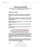
Electrons are given energy by the voltage provider (in our case a 2V power pack), which propels them into the conduction band. However, there are still small atoms in the way of the electron, and electrons don’t move from side to side to avoid obstacles. Every time an electron hits an obstacle it slows down and gives off some energy, thus the flow of current is reduced and the wire becomes slightly warmer.
The power pack must not be used for producing currents of more than 1A, and so our experiment will need to incorporate a variable resistor. This means that we can control the voltage across the wire and so get an equation for resistance R = V / I .
We can then get another equation for resistance from the “Salters Horners As Level Advanced Physics”, where resistance R = ρ l / A
So because;
Resistance= Voltage = Resistivity x length
current area
We can rearrange this formula to get;
Current = Voltage x area
Resistivity x Length
As we have known values for voltage, area, resistivity, and length, I can calculate predicted results, and draw a predicted graph.
For example at a length of 50 mm
Current = 0.2 x (9x10-8)
(110x10-8) x 0.05
Current = 0.33amps
I repeated this with every length of wire I plan to test, and have calculated the following predicted results.
Diagram
Apparatus
- 1m nichrome wire, 26swg
- Power pack
- Variable resistor
- Voltmeter
- Ammeter
- 2 crocodile clips
- ruler
- 6 wires
- Micrometer Screw gauge
Method
- Set up circuit as shown in above diagram
- Determine the length of wire used in each experiment by adjusting the length between the crocodile clips.
- Measure width of wire using screw gauge micrometer.
- Begin with an experiment wire of 50mm.
- Adjust the variable resistor so that the voltage in the circuit is 0.2V. (measured on voltmeter)
- Record the current in the results table.
- Turn the experiment off.
- Increase the gap between the crocodile clips to 100mm
- Reset the voltage to 0.2V using the variable resistor.
- Record the current in the results table.
- Continue using this method until you have recorded experiment wire lengths every 50mm between 50-600mm.
- Repeat the experiment 3 times.
Safety
I will make the experiment safe by using a low voltage. I will turn off the experiment when changing the distance between the crocodile clips. I will not leave the experiment running for too long, as the wire will get hot and burn the table. I will keep the experiment away from water. I have used a variable resistor to ensure that the current does not exceed 1amp. This will prevent short circuits.
Fair Test and precision
I have kept the experiment fair I will control all factors, with the exception of length. I will keep the voltage in the current constant by adjusting the variable resistor. I will use the same piece of wire each time, this ensures that the type of wire, and diameter is the same. I will turn off the circuit between readings. This will prevent the wire heating up, which would increase resistance in the wire.
I plan to take all measurements to the nearest 2 decimal places, and length to the nearest mm (except in the case of the micrometer screw gauge, which is accurate to the nearest 0.01mm)
Results
I measured the diameter of the wire in 5 places using a micrometer screw gauge.
Results of Length against current (using 26swg nichrome wire)
I have then used these results to find out the resistance compared to the length of wire. To calculate this I used the formula ‘resistance = voltage / Current’ as I have a constant voltage and a known current.
Conclusion
As length of wire increases, resistance increases and so the current decreases. This is proven by my graph of collected results, which shows an exponential curve (1/x). This is because as electrons flow through a wire (creating a current) they collide with fixed particles. Every time an electron collides with an obstacle it slows down, and looses energy in the form of heat. This restricts the flow of current. In a longer piece of wire there are more particles, and so the electrons collide more frequently. This is why resistance increases, and current decreases.
The graph showing length of wire against current proves that as length increases, resistance increases proportionally. The best fit line for this graph is a straight line. Resistance increases as length increases because in a longer piece of wire, there are more particles to restrict the flow of electrons.
I have plotted my predicted results and my collected results on the same axis, in order to compare them. I have also added exponential lines of best fit to each set of results. They both show the same shape curve, but my collected results all show a slightly higher current. This means the resistance must have been lower than I expected.
I can use the formula R = V / I to show that as resistance increases, current decreases. First I need to rearrange the formula to I = V / R. Because voltage is a known, constant value (0.2V) as resistance increases, current decreases.
e.g.
I = 0.2 = 0.1amps
2
I = 0.2 = 0.05amps
4
This proves that as current decreases when resistance increases.
Because I know the current which flows through different lengths of wire under my controlled conditions, I can use the formula R = V / I to calculate the resistance at different lengths of wire.
e.g.
R = 0.2
0.31 (current at 50mm) = 0.65 ohms
R = 0.2
0.05 (current at 550mm) = 4 ohms
This proves that as length of wire increases, resistance increases. I have already proved that as resistance increases, current decreases. This is why my results and graph show that as length increases, current decreases.
My collected results prove my prediction because my predicted results and collected results both show the same relationship between length and current.
Evaluation
My method was accurate enough to be able to prove my prediction, as they showed a strong pattern, and there were few anomalies. If I were to re-do the experiment I would repeat it more times to make my results more accurate. I would leave the equipment longer in-between experiments to give it enough time to cool down.
Anomalies occurred in my collected results. At a length of 100mm the current was higher than expected. This means that the resistance had decreased. The factor that changed this resistance was room temperature. The room must have been slightly colder when this reading was taken. This also occurred at a length of 500mm. At a length of 200mm, the current was lower than I expected. This means that resistance must have increased. Temperature increase is a factor that makes resistance increase. This result could be from the experiment being left running too long. The temperature of the wire would have increased, increasing resistance and reducing current.
My predicted results for current were all slightly lower than my collected results. This means that the resistance must have been lower than I calculated for my predicted results. The factor that effected resistance was room temperature. In my predicted results, the value for resisitivity of nichrome I used was for a room temperature of 20°c, whereas the room temperature when I carried out the experiment was about 18°c. At a lower temperature, the resisitivity of nichrome was lower. This would explain why my collected results all have a higher current than I expected.
If I were to extend the investigation into 'factors effecting current flowing through a wire' I would investigate another factor. Possibilities are diameter, temperature, voltage, and resistance.
Nicola Dearnley 10a1, 10fm