If V , V2 and V3 are the potential difference across each of the resistors, R1 , R2 and R3, applying Ohm’s law to each resistor would give:
Note that, the total voltage across all resistors is equivalent to the voltage of the battery. Thus we have:
The equivalent single resistance, Req that would draw the same current, I, would be related to V by:
Since V= IR then we would have:
Since the potential differences must be the same as the emf of the battery, then we have:
Note that the equivalent resistance is greater than the greatest resistance of any of the individual resistor alone. The SI unit for resistance is ohm, Ω
Resistor in parallel
When two or more resistors are connected as in the below, they are said to be connected in parallel.
We let I1, I2 and I3 be the currents through each resistor R1, R2 and R3, respectively. Because electric charge is conserved, we can say that:
Each resistor experiences the same voltage which is equal to voltage of the battery, V, so, by applying Ohm’s law to each resistor, we have
The equivalent single resistance Req that would draw the same current, I, would be related to V by:
Combining both equations, we would obtain:
Now, if we divided the equation by V, we would have:
Note that the SI unit is still ohm, Ω
Apparatus
- Computer and science workshop interface
- Power interface
- AC/DC Electronics Lab board: Wire leads, resistor, 3V light bulb
- D-cell battery
- Digital multimetre
- Banana plug patch cord
- Resistors
Procedure
Part 1: Measuring current and voltage.
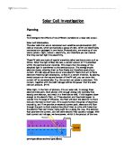
- One of the resistors is chosen and by using the chart provided, the resistance value is decoded and recorded in the first column of Table 1.
- The circuit is constructed by pressing the leads of the resistor into two of the springs in the experimental section on the Circuit Experiment Board as shown in the figure below.
- The multimetre is set to the 200mA range. The circuit is connected and the current that is flowing through the resistor is read and recorded in the second column of Table 1.
- The resistor is remove and another resistor is chosen. The resistance value is recorded in Table 1. The current is then measured and recorded as in step 2 and 3. The process is continued with measuring all the resistors given.
- The multimetre is disconnected and the wire from the positive lead (spring) is connected directly to the first resistor used as shown in the figure below.
- The resistor is remove the next one used is chosen. The voltage is recorded in Table 1 as in step 5. The process is continued until all the resistors’ voltage recorded.
Part 2: Resistance in circuits
- Three resistor of the same value is chosen. The set of colours is recorded in Table 2.
- The coded value of the resistors is determined and the value is recorded in the column labelled “Coded Resistance” in table 2. The tolerance value is entered as indicated by the colour of the fourth band under “tolerance”
- The multimetre is used to measure the resistance of the three resistors. The value is then recorded in Table 2.
- The percentage experimental error for each resistance value is calculated and is recorded
- The three resistors are connected to the series circuit by using the spring clips on the Circuit Experimental Board to hold the leads of resistors together without bending them. The resistance of the combination is measured as indicated on the diagram by connecting the leads of the Multimetre between the points at the end of the arrows.
- A parallel circuit is constructed by using the combination of the two resistors and finally by using all the three resistors. The values for the circuits are measured and recorded.
Part 3: Voltage in circuits
- The three equal resistors used in Part 2 are connected into the series circuit as shown in the figure below using the spring to hold the leads of the resistors together without bending them. Two wires are connected to the D-cell correctly.
- The voltage function on the multimetre is used to measure the voltages across the individual resistor and then across the combination of resistors. The reading is then recorded.
- The parallel circuit is connected using all thee resistors. The voltage across each of the resistors and then the combination is measured.
Part 4: I-V Characteristic curves for a typical resistor and a filament bulb
- The science workshop interface is connected to the computer and then the interface is turned on.
- Data is recorded via the voltage and current sensor.
- The start button on the Science Workshop taskbar is pressed. The bulb’s filament will start to grow progressively to a certain maximum brightness before it goes off. At the point it goes off, the stop button is pressed.
Results
Part 1: Measuring current and voltage.
Table 1
Part 2: Resistance in circuits
Table 2
Table 3
Part 3: Voltage in circuits
Table 4 (series)
Table 5 (Parallel)
Part 4: I-V Characteristic curves for a typical resistor and a filament bulb (graph)
Calculation
Part 1
In part 1, we are required to calculate the ratio of voltage/resistance by using the formula:
I = V
R
1. 1.477 = 0.147
10
2. 1.478 = 0.014
100
3. 1.478 = 0.004
330
4. 1.481 = 0.002
560
5. 1.482 = 0.001
1000
Part 2
In part 2, we are required to calculate the percentage of errors and compare to the coded tolerance by using the formulae:
| Measured resistance - Coded resistance | X 100%
Coded Resistance
R1= | 101-100 | X 100%
100
= 1 %
R2= | 102-100 | X 100%
100
= 2%
R3 = | 101-100 | X 100%
100
= 1%
Discussion
From Ohm’s Law, we can conclude that the voltage, V is proportional to the current, I. Thus we have:
V α I
R α 1
A
Thus when the graph is constructed,
All three graph followed Ohm’s Law. The law itself state that current is given by the ratio voltage/resistance. The data that is obtain through the experiment proves Ohm’s Law even through it still have a small percentage of errors which might due to random errors. In this experiment, errors can be made in many ways for instance the data is not calculated properly, the wires are not connected properly or even when the multimetre is not read properly.
In part 2, the coded tolerance for the resistor is +5%. From the reading we obtain the percentage of errors is 1% and 2%. Thus it said that the data obtain is acceptable. In part 2, we conducted two experiment whereby in one experiment the resistor is arrange in series and in the other experiment the resistor is arrange in parallel. Base on the theory for series resistor we have:
Thus the equivalent resistance in the circuit is:
The rule for the total resistance when the resistor is arranged in parallel is as followed:
As a conclusion we can say that the data obtain in the experiment obey the rule.
In part 3, we found out that the voltage gets distributed in a series circuit with equal resistance when the value of the resistor is the same. The larger the value of the resistor, the larger the value of the resulting voltage.
In part 4, a voltage versus current was obtained. At a certain point in the graph, a straight line is obtain which directly prove Ohm’s Law which stated that the voltage, V is proportional to the current, I and the slope of the graph is the resistance.
Conclusion
As a conclusion, we found out that the voltage, V is proportional to the current, I. The relationship for the variable V, I, R is V = IR