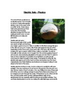
Some devices let a large current through them. These devices have a low resistance to the flow of current. A device with a high resistance allows less current to flow through it when the same voltage is applied. Resistors pass a certain amount of current for a given voltage. High value resistors let a small current pass, and a low value resistor allow a large current to pass. Standard resistors have their resistance clearly marked and some value showing the maximum current allowed without overheating.
I will now be carrying out my experiment with the resistor.
The table of my results from this experiment with the resistor are listed below; in the table I included the volts, milliamps and the amps.
Resistor Table:
Conclusion from Resistor Results:
From looking at the table that I have produced from my results you can obviously see that as the volts increase so does the milliamps and the amps, this is because the charges in a current push past the atoms in a wire, and the stronger the push the higher the milliamps and amps. It also shows that when I drew up my graph there is a curve forming as I plot the points, and the will become more noticeable when I draw up a growth curve.
Light Bulb Table:
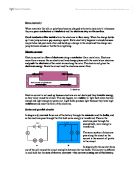
Conclusion from Light bulb Results:
The results on this table are similar to the ones on my resistor table, as you can see, as the volts increase so does the milliamps and the amps (current) this is because there is a stronger push to allow more currents to pass through the voltmeter, when I draw up my graph they will also be a curve just like the resistor table but it will be slightly different because of the results. From comparing my light bulb table and my resistor table I managed to identify that at 10volts the light bulb was at 6.76Milliamps and for the resistor it was at 5.22Milliamps, there is a big difference between the two and this instantly tells me that the light bulb has less resistance than the resistor does (obviously) this is because the light bulb allows more currents to pass through probably because of the material of the light bulb or the resistance is just low.
Section B: Electrical Devices:
Aim: I must investigate and explain how an electrical device works. This device must have motorised parts in it. In my report I need to explain the following parts:
- Power Supply
- Input Section
- Procession Section
- Output Section
- Motorised/ Mechanical Section
In section B the electrical device that I will be investigating will be a CD Player I will be investigating a CD player because it is not to big and complicated like a microwave oven or and television, a CD player will be easy to investigate because it has a small motor inside its input device is simply a Music CD and its input section are the lens of the CD player, and its output section is the earphones where the sound energy is released but I will be writing about this with more details in this part of the coursework.
I will now write about the CD Players Power Supply and so on:
- CD Players Power Supply: Most of the CD players that I know about obtain their power from batteries; batteries are a form of chemical energy because the energy is stored. Other forms of chemical energy are also fuels, electrical cells, and all foods such as bread, butter and others that contain carbohydrates and fats. Chemical energy is useful in many ways, especially in form of batteries because they can be used whenever needed and not wasted like most forms of energy such as a light bulb, light bulb looses plenty of heat energy, which is wasteful.
- CD Players Input Section: The CD Players input section is most likely to be the lens inside the player, the CD is inserted into the player and when the CD spins the data from the CD is being transferred from the CD to the player through the lens, this is the most likely input section because I there is no other input section that I can think of not unless it’s the audio-amp.
- CD Players Output Section: The Output Section for the CD player is quite obvious; it can only be the earphones. To reach the output section it firstly needs energy and this is obtained from the battery as chemical energy, the CD player will now be working and the lens (or audio-amp) which is the input section will be transferring the data from the CD and then this will then come out through the ear phones/speakers as sound energy.
- CD Players Motorised/ Mechanical Section: The CD Players Motorised section has to be the motor that keeps the CD spinning, this is where all the main things are happening in the player, and without this there is no chance that the CD Player could even work. The motor in the CD player works like how any other basic motor works, it works using an electromagnet that spins using magnetic forces.
Below is a diagram of a circuit diagram of a CD Player:
Section C: Making an Electronic device:
In this part of the coursework I will have to make an electronic device. I will not need to know exactly how it works. I must keep a diary of what I do. I will produce a report that includes the following sections:
- What problems did I have in the project and how did I solve them?
- What extra safety precautions do I need with specific equipment?
- A record of how I tested my final circuit.
- Suggestions of any possible improvements.
- A comparison of my project to how it might be done by a professional company.
Day 1 and 2:
When carrying out this experiment I firstly gathered all the equipment that was needed for me to make my electronic device, the equipment are listed below as followed:
- Wires (Amount unknown)
- Resistors (Amount unknown)
- Counter Chip
- Decoder
- Seven Segment Display
- Capicator
- LDR
- Small light Bulb
We are given only a few days to complete our electronic device, so I done it as quickly as possible!
When I had all my equipment I firstly thought about the method I would use for me to create my electronic device, and then I finally thought up the idea…
- When creating my electronic device I begun by firstly putting all the wires where they were suppose to be fitted into, and by doing this it made it more easier for me to identify where all the other vital parts for the electronic device needed to go. When putting the wires where they needed to go it took me a maximum of two days to do because a few mistakes were made but they were eventually corrected.
Day 3:
This was the last day I had for me to complete my electronic device so I had to be 100% focused on what I was doing and have full concentration on my experiment.
-
On the 3rd day I was careful when fitting all the other parts such as the light bulb and the Seven segment display onto my electronic device because if I made one slight mistake there would’ve been a chance that I would’ve been too late to correct it because this was the last day, when I had completed it and everything was fitted in place I then had to test my electrical device by attaching one red wire and one black wire from my device to a power pack, and what should happen is that the small screen on my device should’ve counted up to 5 in five swift seconds and the light should’ve lit up every one second and it did! So this instantly told me that I was successful in this experiment.
Report:
- What problems did I you have in the project and how did you solve them?
Answer: I had a few problems such as putting all the components together in making my device such as the wires because it began to get confusing after a while, but I managed to solve the problem by changing my method of how I will create my device, and what I done is I decided to put the wires in first then the other components. I also had a problem of getting the wires into the holes but this problem was solved by getting longer wires because the wires I started off with were too short.
- What extra safety precautions do you need with specific equipments?
Answer: I had to take safety precautions when I was testing my device with the power pack, power packs can become highly dangerous if used in the wrong way, I also had to take care with the wire because the metal ends are quite sharp and are able to cut through the human skin.
- A record of how you tested your final circuit.
- Answer: I attached it to a power pack and I firstly tested if it came on at all and it did, so I passed that test.
- Answer: I then tested if the screen counted from 1 to 5 in 5 swift seconds, and it also passed this test.
- And the last test was to see if the little light lit every one-second, and it also passed this test.
- Suggestions of any possible improvements.
Answer: The only improvement that I could suggest would be to do a different type of circuit such as a parallel circuit and see what we come out with, we could also try using different components in our device and another idea would be to increase the current, but not to high. But the only improvement I can definitely go with would be to try a parallel circuit.
- A comparison of your project to how it might be done by a professional company.
Answer: I am about to compare the way my project was done to the way it would’ve been done in a professional company.
In a professional company they would not have constructed their electronic device using the same method that I used when I was doing mine, in a professional company they use robots to make the electronic devices and they also have quality control systems to test the circuitry. They also have printed circuits when it is done in Proffesional Company and they also have automatic constructing techniques when constructing the electronic devices in a professional company, the device is passed along through steps where more parts will be added on after each step and this method is a lot quicker than the method that I used.
Bibliography: