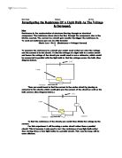
For this experiment I will need to have the following:
1. Power pack which will be able to increase the load
Of power.
2. An ammeter to measure the current
3. A voltmeter to measure the voltage.
4. A bulb
5. Several wires to connect up the circuit.
Shown on below is the equipment set up in a diagram.
Ohms law states that: the current flowing through a conductor is proportional to the potential difference across it providing the temperature is constant. So therefore if ohms law is kept, the relationship between Voltage, Current and Resistance is that R=V/I, V=IR and I=V/R.
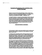
The factors that can affect the resistance of a piece of wire are the thicknesses i.e. thicker wire the lower the resistance, as the electron flow has a larger volume to travel through than with a thin wire. The type of metal used for wire i.e. different bonding of electrons can affect the resistance of a piece of wire. Metals in which the electrons are more loosely bound to the nucleus have a lower resistance than those metals where the electrons are held more tightly. Also the temperature can affect the resistance.
The diagram below shows inside a piece of wire showing the free electrons-the flow- and the metal ions. If the temperature is increased then the free electrons in the diagram will hit the metal ions more creating more resistance. If the thickness of the wire was changed i.e. when the metal is thinner the free electrons will have a smaller area to pass through and will hit the metal ions more and so there is greater resistance, than in a thicker wire where there is a greater area for the electrons to pass through. Therefore it will be easier for the free electrons to move through a thicker wire and the resistance is therefore lower.
I believe that if the Voltage and/or the current are increased then the light bulb filament will get brighter and the resistance will go up because the temperature changes. This breaks ohms law as the temperature changes so therefore the resistance will change. You can tell that the temperature rises because of the colour of the light bulb filament. If the light bulb filament is an orange colour at around 2 volts this shows the temperature is not very hot but if the volts are increased to 8 volts then the light bulb becomes white hot showing that the temperature has raised. This is rather like the colour of a fire showing us that if the fire glows red it is not as hot as when it is white hot. Therefore the white filament shows the temperature has risen which therefore increases the resistance of the filament breaking Ohms Law which is only true for constant temperature. If the temperature of a filament bulb is increased the metal ions will vibrate more this means then an electron is more likely to hit a metal ion and therefore the flow of electrons is reduced. Therefore there are more collisions between electrons and metal ions which causes more friction and thus a rise in temperature and a rise in resistance.
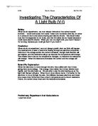
I believe that if the Voltage and/or the current are increased then the light bulb filament will get brighter and the resistance will go up because the temperature changes. Below is a diagram showing how I believe the resistance will increase as the voltage is increased. See diagram below on variation of resistance. This information was obtained from ‘Explaining Physics’ by Stephen Pople.
Preliminary Work
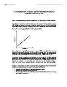
In the preliminary work I put in a variable resister, rheostat. A variable resister changes the resistance in a circuit and therefore changes the voltage and or the current in a circuit. A variable resister can be used in other things like a motor so you can increase or decrease the speed of the motor, and also in a dimmer switch for reduced lighting. Preliminary
I put in a variable resister so I could change the voltage, by altering the resistance, and obtain voltages from 1 – 12 inclusive. Therefore I could get 12 results, rather than six results which I would have got by increasing the voltage on the power pack which stepped up by 2 volt increments. The voltage on the power pack was not very accurate as on the power pack it said 2 volts but the reading on the voltmeter was 1.7 volts, so we added the variable resister so we could change the voltage to make the results fair and more accurate. So now we could measure the voltage from 1-12 volts and would also measure the current for each time the voltage is increased. In this experiment to make it a fair test I would use the same equipment and would especially keep the same light bulb. I would keep the same light bulb due to if I changed it during the experiment the readings would change as all light bulbs filaments have different sized, thickness of wire or the wire has different bonding of electrons which would change the resistance and therefore not a fair experiment. Below is a diagram of the circuit I used in my preliminary work.
What has been found out from the results from the observation is what I predicted. What I predicted and what has happened with this experiment is that when the potential difference is increased is that the current increases and there for this means that the resistance is increased. You can see from my recorded results above and the graphs that are drawn that the resistance has increased as the potential difference is increased. Why this happens is due to it breaking ohms law that states: the current flowing through a conductor is proportional to the potential difference across it providing the temperature is constant. As the temperature is not constant due it increasing in the light bulb filament the resistance changes and therefore ohms law is broken. These results confirm my predictions and are explained by the theory that as the voltage is increased, more electrons flow through the circuit and light bulb filament giving more collisions, and therefore raising the temperature. The resistance of the light bulb increases as it is more difficult for the electrons to flow through the filament as the metal ions are vibrating and slowing down the electrons. The graph of current and voltage shows that as the potential difference increases then so does the current but not at the same rate, see shape of graph, because the temperature increases and Ohms Law is not obeyed. This is also shown to be the case on the other graph of resistance against increasing voltage.
Evaluation
My results from the observation were pretty accurate as if you look above the results nearly all repeated themselves and when in a line graph the line of best fit went through nearly all the points on the graph.
The trend and the pattern on both graphs is that the current and the resistance increases as the voltage is increased. On the graph of resistance two results are out of place. The two results which are out of place are at 4 and 7 volts. On the graph it shows that they are above the line of best fit. The result at 4 volts was 18.18 Ω and I would have had expected it to of been at 17.40 Ω which would then be in the line of best fit. The result at 7 volts was high as well at 23.33 Ω so I would have expected this result to be at 22.90 so it would have fitted the line of best fit in the line graph. These two results were then low on the graph showing average current. I would have expected the result at 4 volts which was 0.22 to have been 0.23 to fit the line of best fit. The result at 7 volts which was 0.30 was low again but I would have expected it to have been at 0.31 so it was in the line of best fit. Also on this graph showing current the second to last result was too low, the result was at 0.39 but I think the result should have been at 0.40 so it was in the line of best fit.
These results show that if the resistance on the resistance graph is too high it will then be lower on the current graph.
I think that some results are wrong due to the rheostat being unreliable. One reason for this could have been that the rheostat could have had a loose connection. Also the coiling of the wire in the rheostat could have become pulled apart with use and this could make the rheostat inaccurate. I tried to avoid this by checking if any rheostats worked better but they did not work as well. To have solved this the school could have had some new rheostats.
My results were good enough to support the prediction and for this reason I think my investigation was worth carrying out.
Further work to this experiment could have been done with a new reliable rheostat which would give me more accurate results. Also I could have changed the make of the light bulb to see if a different make of light bulb would have given similar results and verified the prediction. Using a different light bulb may give different results as the metal filament may be different but the general pattern should be the same.