I am going to use two LDRs connected in series on a piece of card at varying distances apart to find the effect of the light shining on them. This is the circuit that I am going to use.
Circuit diagrams
As you can see when the light levels are the same, the voltages are the same.
When the light levels are different, the voltages are different but it still adds up to 12v overall. The voltage is the same, it is just shared out differently. When the light level is high (400), the resistance is high and therefore the voltage is low. When the light level is low, the resistance is low and therefore the voltage must be high. Voltage always equals current x resistance.
I am hoping to use a motor to respond to the difference in voltage or resistance and move to the direction of the light. It will stop when the voltage is the same on both sides i.e. when the light is in the middle of the two LDRs. They will act as like eyes, locating the light source.
The two LDRs are going to be separated by a sheet of card straight down the middle of the card that the LDRs are mounted on. This is so the light falls on one or the other of the LDRs. It will cast a shadow so one of the LDRs will be in perfect light and the other will be in near darkness. As the light nears the middle, the light will fall equally on both. By doing this I am emphasizing the amount of light on the LDRs, creating a bigger difference and more emphasized results. I am taking the results of the voltage of one of the LDRs. If I took the voltage of both of them, it would always read 12v. The lamp that I am going to use is 12v, 90watt bulb and it is going to be placed 15cm away from the LDRs and it will be moving from right to left at 5cm intervals in front of the LDRs so it will be shining at them from different angles and more importantly, shining on one of them more than the other. It is 5cm because it gives lots of different positions the light can be in so produces a wider range of results.
Results
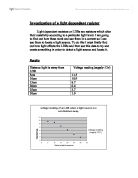
In the results that I obtained, I took 3 readings from each distance and took the average of these three to try and eliminate anomalies and get an accurate result. The results I took were the voltage across one of the LDRs If I took the voltage across both it would be 12v all the time. If I took the voltage readings from the other LDR it would be opposite i.e.: 12 – the voltage reading of the 1st one
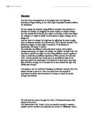
As you can see from this graph, the results are irregular and hard to interpret. The LDRs at 5 and 15cm away seem to follow a similar pattern but the LDRs at 25cm away is irregular and doesn’t follow the trend. I think this could be due to anomalous results and the light levels outside. If the light intensity outside should change it could affect the results of the readings. The 25cm away result seems to be an inverse of the other two. It is high where the other two are low and it is low where the other two are high.
Another reason for the irregularity of the results could be to do with the section of card that was placed between the two LDRs. This could have cast a shadow on one of the LDRs while the other was in full light causing the difference and unpredictable nature of the results. As the light moved closer to the middle, the shadow would have got shorter and then disappeared when it hit the middle (40cm). This is apparent by the way that at 40cm all of the reading are the same. When the LDRs are only 5cm away from each other, the shadow will cover it more and for longer, producing the more dramatic set of results.
Because the piece of card stayed the same and didn’t change, when the LDRs are further away from each other, the shadow doesn’t affect the results as it would the other two sets. This could explain why the results for the 25cm result seems inverse to the others, the shadow isn’t reaching the LDRs now because they are further away from each other.