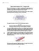
Fingers represent:
Thumb shows the direction of the movement ( the force )
The first finger shows the direction of the field
The second finger shows the direction of the current
The production of this force is known as the motor effect, because this force is used in electric motors. I a simple motor, a current flowing in a coil produce a magnetic field; this field interacts with a second field produced by a permanent magnet.
Magnetic flux is a measure of quantity of magnetism, taking into account the strength and the extent of a magnetic field. the flux through an element of area perpendicular to the direction of magnetic field is given by the product of the magnetic field and the are element. More generally, magnetic flux is defined by a scalar product of the magnetic field and area element vector.
Magnetic flux density used to describe the amount of flux flowing through unit area at a point in the field. The symbol used for flux density is B, and its unit is the tesla, T.
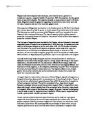
In this experiment, I am going to use a current balance to investigate the force on a current-carrying conductor in a magnetic field . A current flow through the wire frame; the magnetic field pushes the frame downwards, we can work out the direction of the motion by using the Fleming’s left-hand rule. By adding small weights to the other side of the frame, I can finally make the balance go the equilibrium. There fore the magnetic force is equal the restoring weight. In this case, I will use some little pieces of paper as they are small and light enough to get an quite accurate mass value.
The size of the magnetic force depends on:
The magnetic field strength, B
The current I, flowing at right angles to the field
The length l of the conductor I the magnetic field. ( in this case, the length of the conductor will be the length of the magnet)
Sum up these three factor, we can get an equation for the force:
F = BIl
We can see from this equation that the force F, is proportional to each of these quantities.
we can arrange the formula:
B = F/Il
A magnetic field has a strength of one tesla ( 1T ) , if it exerts a force of 1N on a conductor of length 1m, carrying a current of 1A at right angles to the field. Thus the equation b = F/Il defines the quantity magnetic field strength( flux density) B, and its unit, the tesla: 1T = 1NA-1m-1
As the force of magnetic is equal to the restoring weight, the length of the conductor can be measured by measuring the length of magnet, and the current can be measured by an ammeter. Therefore the magnetic flux density can be calculated easily.
There are few factors which I think would affect my experiment:
The current flowing in the wire
Because the stronger the current, the bigger the magnetic field it is generated, therefore the magnetic force would be bigger. As I am going to find out the magnetic flux of the magnet not the wire, so this factor is not going to be concerned. And also I will use a variable resistance to vary the current to get different values so that enable me to plot a graph.
The material the core is made of
Different materials have different resistivity, so that the amount of current flow in each material is different. In this case, I am going to use copper wire because it has very little resistance so that current can easy to flow.
To keep this a fair test and get a reliable and accurate results, I will use the same wire as it will have the same amount of resistance and I will use the same balance each time to weight my stored papers so that to give me the same accurate figure. The same power supply will be used as some power supplies give out different voltage even if the difference is small.
Equipment & Justification
Tow magnets (which have the exactly the same size).
This ensure that they have the same length( length of the conductor in the magnetic field) and the same magnetic flux.
D.C power supply
This makes the current flow in the same direction.
Current balance with copper wire on it
Less resistance, current can easy to flow
Small paper pieces
These are used to add to the other side of the frame, and make the current balance go the equilibrium. As they are small and light enough, so that to give more accurate results.
An electronic balance
As it is electronic, and it will give the value up to 2 decimal places, so that produce more accurate results.
Copper wires
Variable resistor
This is used to vary the resistance in the circuit to give different current.
An ammeter
This is used to measure the amount of current
Safety
Wearing goggles
Watching out the current, if it gets to large, the wire could be burnt or get to hot. Make sure do not touch the wire if it gets too hot.
Method
- set up equipments like the diagram
- switch on the power supply and vary the variable resistance, record the current shown on the ammeter and adding paper pieces on to the frame
- as soon as the current balance goes to equilibrium which can be seen by comparing the level of two frame on each side, to see if they are at the same level, and switch of the power supply
- carefully moving the stored paper on to the balance and record the mass shown on the screen
- changing different current by varying the variable resistor and do the same steps as above
- repeat the experiment with the same current
- calculate the average mass of paper for each current and use the average to plot a weight—current graph
- tidy up the equipments