When I first asked for my apparatus, I was going to ask for a light gate but it was bought to my attention that there was not able to use one. Therefore I had to revise my thoughts on apparatus. I came upon the idea of a rotary potentiometer (mentioned above). Unfortunately I could not get hold of a hairdryer either but this was easily overcome because I had a Hoover with a blow function suitable for use in my experiment!
My final list for apparatus looked like this: - Clamp (x3)
Stand
Extended Stand
Boss (x3)
Hoover with blow function
Rotary Potentiometer
Sheets of Cardboard
Power Pack
Ammeter
Voltmeter
Leads
I only had one slight worry, which was that; my rotary potentiometer would be too stiff, to be turned by the force of my Hoover. So, I decided that I would oil it, hoping this would act as lubrication freeing up the spindle so it could turn without restraint therefore I would get better readings. I let the resistor dry out I then checked that the oil had not affected the electronic circuitry within the potentiometer, I did this by wiring it up and rotating the spindle checking the current on the ammeter. The spindle now turned very freely so I hoped that the sensitivity of the circuit would have improved.
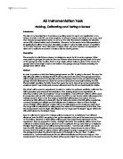
Measuring the current was an easy method of recording how far the potentiometer turns; I am only using two of the connections on the potentiometer so I am essentially using it as a variable resistor. I had to measure in the scale of 200μ Α on the ammeter. The (50K) potentiometer will be connected to an ammeter and a voltmeter. I will aim to keep the voltage constant and then record the fluctuation in current. This will be possible due to the design of the circuit (see left). To turn the current and voltage to the resistance I have to use the formula: R=V
I
Setting up the apparatus
The apparatus was fairly simple to set up (see diagram below)
I one real problem when setting the apparatus like this, which was I had to make sure that the
Nozzle of the Hoover was pointing directly into the centre of the vane. I did this by measuring
the distance from the centre of the vane to the ground and then calibrated it against the distance
from the centre of the nozzle and then to the ground.
Unfortunately setting it up in this manner the flow of air is not concentrated into the vane,
it spreads out from the source. The further away you are the more spread out it is. Therefore it
does not produce a totally accurate reading, but it still obeys certain rules. The air flow hits the
vane and we only need to consider the area of the vane.
For example. a : b (linear ratio) then it implies that a2: b2 (area ratio) is correct. See diagram.
If this correct then it is also true for the (volume ratio) a3 : b3 because as the air is blown from the source it spreads out in a cone.
The fact that the air blows in a cone becomes slightly irrelevant because the airflow is always going to be striking the same area; because the vane doesn’t change in size it is always going to be 64cm2. So we can use it according to the area ratio.
The 8cmx8cmx8cm open-faced cube only becomes affected by the fact that the “wind” blows in a cone, when the distance changes between the vane and the wind source. When the distance is doubled the amount of air hitting the vane is multiplied by a quarter. Similarly when the distance is tripled the amount of air hitting the vane is multiplied by a ninth.
We can write this universally by saying when the distance from the nozzle to the vane changes from x to kx
The force of the air striking the vane is multiplied by the reciprocal of k2. Implying that the further away the airflow is from the vane, the less powerful the stream is acting upon the vane.
Distance is: A possible theory for the amount of air striking the vane is (F):
x : kx F α 1
k2
Area is:
x2 : kx2
This expression is known as “The inverse square rule”.
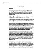
I know my calibration curve approximately follows this equation because of the shape of it. The calibration curve was formed by plotting amps against distance from wind source, as you can see the curve seems to show that the experiment was reasonably calibrated. The experiment seems to follow my rule and it seems to abide by the inverse square rule.
Evaluation/Improving sensitivity
- The experiment itself had lots of places where errors were likely to have been made. Both the practical and theoretical side of this turned out to be far more complicated than previously expected. I found often myself struggling in certain areas due to the gaps in my knowledge. Though my results were encouraging.
- I think from the very beginning that this sensor was always going to be hard to be made sensitive and/or accurate. From the start I did my best to achieve a high amount of sensitivity, I did this by oiling the potentiometer so that it would turn more freely. I also tried to use also tried to construct a shape of vane, which would continually have the greatest amount of “wind” hitting it, although I was restricted due to the amount of card which I had at my disposal. I would have liked to make the wind vane larger there for it would have been complicated to work out the calculations.
- Something else I thought about was to do with the weight of cardboard and whether I could use something lighter i.e. paper, but I realised it would have to be sufficiently stiff so that it wouldn’t crease or fold when attached to the spindle of the potentiometer.
- I could have possibly made the sensor more responsive if I was to use higher voltage, this would have given me higher readings and therefore hopefully less errors. Though I would have to be careful not to use a too large voltage so that it wouldn’t become dangerous for the person using the apparatus.
- In a classroom there are always drafts whether it is from leaving the door open to someone walking past a bench swiftly. This could have possibly affected my results. I know that a student behind me was also doing a similar experiment and their “wind” could have possibly affected my sensor.
- I have explained above how I had to calibrate the height of the nozzle to the height of the vane. This could have been knocked off line when I moved the nozzle closer or further away from the sensor, I could have got round this by re-measuring the height and re-aligning the whole experiment.
- Probably the most important thing to do next time (If I was to redo this experiment) would be actually record the wind speed from certain distances. So I could try to find a relationship between the resistance and the wind-speed. This would allow me to see whether any of my previous calculations above are correct.
Percentage Errors
We can see how inaccurate the apparatus was by performing a few percentage error calculations.
As you can see the percentage errors are so small that it is probably justified not to take them into account, but I did only take two sets of results, so it could be more if I had time to take more results.