The intensity of the magnetic field varied in the same way as the current (and so the original sound) recording tapes have a thin plastic tape coated with a thin layer of ferric oxide powder – which can be permanently magnetised by the magnetic field.
If several microphones are to be recorded together – an electronic box called a mixer is used to balance the relative strength of the signal.
During playbacks the reverse process of the above happens, the tape passes through the playback head where the tape’s magnetic field induces current in this head.
The currents are amplified and the electrical signal is passes to a loudspeaker where it is converted into sound by mechanical vibration of the loudspeaker/
Storing data is easier if it is digital i.e. compact disks (CD) and MP3 players. To produce digital data, the analogue signal must be sample at the recording stage.
The signal voltage is measured at regular time intervals and the measurements are converted into binary numbers. However, when a sound is played, the binary data must be reconverted into an analogue signal to drive a loudspeaker:
Microphone produces analogue signal. Analogue to digital converter (ADC) digitalises this analogue signal into binary
Digital signal processor (DSP) analyses the digitalised signal – encoding it using a compression algorithm. The compressed data is stored in memory.
Upon playback, data is retrieved from memory and is decompressed. DAC changes the digital value back to an analogue signal. A speaker or amplifier will then play the sound.
Routine used in DSP is called codec – for compression – decompression, common codecs includes MP3 and WMA. The sampling of the analogue voltage occurs at regular intervals of time.
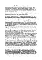
The more frequently the data is sampled, the closer a regenerate wave will be to the original analogue waveform. The rule to set out the minimum sampling rate of a regular signal is that it must be at least twice the frequency of the signal.
If not, the regenerated signal can produce false sounds called aliasing. When sampling occurs at more than twice the signal frequency, then a reasonable signal is regenerated.
When sampling occurs at the signal frequency, there is no signal generated at all, as it would produce a constant voltage. Again, if sampling rate is less than twice the frequency, a very different signal is regenerated 0this signal is called an alias.
The greater number of bits a sampled data is represented by, the closer a regenerated wave will be to the original analogue waveform. However, greater number of bits means more storage space required, so there must be a compromise between storage space and quality of signal.
If an 8 bits binary number is used to encode the same signal, there are now 28 = 256 possible values so quantisation error is smaller. A 4-bit encoding takes up twice the storage space than a 2-bit encoding.
The sequence of binary number that result from the sampling process is known as the pulse code and the process of assembling the sampled analogue signal into a sequence of binary number is called pulse code modulation.
The pulse code is transmitted and when it is received, it can be stored / processed immediately by a pulse code demodulator, which coverts each binary number into a quantised voltage pulse – reforming it into an analogue signal.
Data compression techniques are used to speed up digital data transmission and to reduce space needed to store it by eliminating redundant information.
Lossy compression: certain frequencies received by ears are masked by other louder frequency so those become redundant and needn’t be recorded.
As our ears are more receptive to some frequencies than others so presence of those favoured frequencies masks others occurring at the same time – leading to possibility of elimination.
Predictive coding: previous samples produced information that can predict the next sample, so only the difference between the samples need to be transmitted in order to produce the second sample.
However, if the compression is too extreme, it will produce a noticeable decrease in sound quality. The last technique is used commonly when transmitting digital TV where much of a picture remains unchanged from each frame.
Digital filters remove random noise form a signal / to extract the useful parts of it. I.e. sending high / low frequencies to different loudspeakers in a sound system. Low pass filters remove high frequency and drives a subwoofer (bass player), whereas a high pass filters drives a tweeter (treble speakers) and removes low frequencies.
A digital processor is used to perform numerical calculations on sampled values of the signal, the results will represent sampled values of the filtered signals, and these are output through a DAC to convert the signal back to analogue form. This can be used to eliminate clicks and hiss when analogue ‘vinyl’ disks are converted to CD.
Advantages of using digital signals:
EM interference, signal loss and noise can be virtually eliminated.
Digital files can be copied infinite number of times without loss of quality
Can be encrypted so increases protection of data and security.
It can be compressed
Can be shared amongst many devises (i.e. mobiles, PC)
Disadvantages of using digital signals:
Usually when sound is produces, it is in analogue form, therefore it would need to be sampled and then turned back into analogue at playback.
Binary number can’t be heard from speakers or seen on monitors.
CD and DVD
When light form a laser beam passes through a narrow slit, instead of produces a bring dot as an image, lines of lights are produced. This is due to a property of all waves called diffraction. The intensity of the central maximum is much greater than the secondary maxima and its width is about twice of the other maxima.
The interference pattern produced at overlap site consists of bright and dark fringes of equal width. They’re formed from the super position of waves from each slits.
The bright fringes are formed due to in phase waves reinforcing each other – giving it twice the amplitude of a single wave. So waves from each slit either travelled the same distance / their path difference is an n number of whole wavelengths. This is called constructive interfering.
The dark fringes are formed when the waves travel at a path difference of an odd number of half wavelengths, so they arrive at the screen 180 degree out of phase and they completely cancels each other out, therefore producing no light – this is called destructive interfering.
To calculate the spacing between two adjacent bright fringes (w) use the equation:
W =
A transmission diffraction grating is made by drawing lines (normally between 100 – 600 lines per mm) on a piece of glass / transparent plastic. So the light is transmitted by the transparent slits between the drawn lines.
Whereas a reflection diffraction grating has a shiny surface between the lines – so light gets reflected, for example a compact disc acts as a reflection grating.
The diffraction grating is similar to young’s double slit experiment, however the maxima is much more intense, more sharply defined and angles the beams are diffracted through are larger (so can be measured more precisely), the equation:
nλ = dsinθ
n = the order of image
d = the grating space (how many lines per mm)
θ = the angle the image makes with a line normal to the grating
A normal CD consists of a long single spiral track with microscopic bumps recorded which runs from the centre to the outside.
Diffraction is used to help the laser reader keep on target with precision, a three beam system is used, the diffraction grating produced the main beam with a first order diffraction maximum on both side.
The 3 diffraction beams overlaps the track and when the main beam is centred on the track, the reflected light from the 2 side beams should average out to be of equal intensity. But if beams are unequal, the differences can be used to generate an error signal – initiating a process to correct the tracking.
The bumps on the tracks are made to be a quarter of a wavelength high (λ/4), so the light striking the flat part (land) travels an extra λ/4 in one direction and another λ/4 in the other direction.
Therefore, it’s travelled a total extra distance of λ/2 further than if the light strikes the top of the bump (pits). So light reflected from land is delayed by half a wavelength and would be exactly out of phase with those reflected from pits.
The 2 waves interferes destructively (waves reflected from lands), so no light is actually being reflected – meaning the detecting optical sensor senses bumps as binary number zeroes. Whereas the pits produce waves that constructively interfere – therefore it is sensed as binary number ones.
A motor rotates the disc at between 200 to 500 revolutions per minute, the reason for this range of spins per minute is so that the laser can pick up data at the same rate whether the beam is scanning near the centre (moving quickly) or scanning at the outer part (moving less quickly)
DVDs have a much higher capacity for storing music than CDs – due to DVDs having tighter spirals, shorter bumps and a more efficient tracking system.
Also, DVDs often has two layers, where the laser can pass through the first one to the second layer, this increases the capacity even further.
EM waves used for wireless communication
All EM waves have the following properties:
All have ability to reflect, refract (change in direction of light due to passing from one medium to another), diffract (interference of light due to bending around objects) and interfere.
They travel at the same speed of 3 x 10⁸ m/s in a vacuum. They are not affected by the electric or magnetic field.
All follows the inverse square law (when there’s no absorption of waves). They all consists of a vary electric and magnetic field vibrating at right angle of each other and the direction of travel – meaning EM waves can be polarized.
There are overlaps in wavelength and frequency in the EM spectrum, we can distinguish a wave for how it’s produced. Radio and sometimes microwaves can be used to transmit and receive information without connecting wires / fibres.
Most EM radiation is absorbed by atmosphere - blocks all EM waves apart from:
Some radio wavelength
The entire visible region (wavelength of 390 – 780 nm)
The near (to visible) UV – as most are absorbed by ozone layer
The near (to visible) infrared and some far infrared – those with wavelength between 1-20 mm is absorbed by H2O vapour, O2 and CO2 in the air.
Gamma rays and X-rays are absorbed by gas molecules. The atmosphere is transparent to most radio waves, but the atmospheric absorption becomes a problem for waves with wavelength less than 2 cm. Also, the ionosphere reflects radio waves with wavelength longer than a few meters.
All forms of wireless communication rely on a carrier signal such as an EM wave with a particular frequency (higher than the original wave). When the carrier wave is modulated, we can encode information in the carrier wave to be transmitted. Higher the carrier frequency, the more information it can hold.
When the entire signal is received, the carrier wave is filtered out, leaving only the demodulated (original) audio signal behind. Modulation can be applied to any form of EM radiation.
The medium (MW) and long (LW) wave bands on an analogue radio wave uses AM (amplitude modulation) The information is encoded into the carrier wave.
The signal produced would have a greater amplitude variation when the information is a loud sound, whereas amplitude variation would be small when the analogue sound is quite. The modulation carrier wave is filtered by the radio, leaving the original information to be amplified and fed to the loudspeakers.
FM (frequency modulation) is when the information signal modifies the carrier waves by changing its frequency, the two possible changes include:
Overall change in frequency above and below the carrier frequency, this would represent the original signal’s amplitude.
Number of time the frequency changes between these frequency limits per seconds – this represents frequency of original wave.
When a carrier signal is modulated, frequency other than those of the carrier and original waves is produced. Let fc be carrier frequency & fm is modulating frequency. The possible frequency produced ranges from fc - fm to fc + fm this would have a value of (2 x fm).
So, in order to avoid interference with signals from other sources, an amount of the spectrum equal to 2fm based on fc must be allotted to the signal. This value of 2fm is called the channel bandwidths. The frequency on either side of the carrier wave is called the sidebands.
PCM (pulse code modulation) is a digital technique for transmitting analogue data. It is where the amplitude / voltage of the analogue signal is sampled at regular interval and translated into binary number. Difference between the original signal and the translated signal and the translated signal is called the quantising error.
TDM (time division multiplexing) is a technique used to send several PCM / digital signal from different sources along the same transmission line at the same time.
Signals from each source are split into packets of bits and sent in sequence to the receiver from the transmitter. When the signal reaches the destination, they’re reassembled in sequence into a whole signal by a demultiplexer – so the digital signal becomes decoded at the receiver.
Radio Transmission
Surface waves and space waves are both ground waves. Surface waves are for long wavelengths typically 1 km (LW radio waves), reaching the receiver by diffracting around the surface of the Earth. Wave can diffract around object that are smaller than the wavelength (including hills and building)
Surface waves can reach places that shorter wavelength waves can’t; it attenuates by inducing a voltage pulse into the earth’s surface, reducing wave energy.
Vertical dipole aerials are preferred as they vertically polarizes radio waves, so extent which the electric field is in contact with the earth is reduces. No tuning is required for surface waves as a single transmitter covers the whole country.
TV and VHF radio waves have wavelength of a few meter, these cannot diffract around large building/hills, and would require tuning if travelling long distances.
Space waves travel in line of sight / refracts off Earth’s surface to the receiving aerial. The different densities in air means the wave travel faster at the higher part of the atmosphere than the lower parts causing them to diffract. This means that the space waves travels further than might be expected giving reception up to 15% beyond the visual horizon.
In sky waves, the signal sent out radiates towards the ionosphere, the signals are reflected / refracted by the ionosphere, it can be reflected again back and forth between the earth’s surface and the ionosphere giving several skip zone (an area where no signals are received) Sky waves are appropriate for short wavelength waves, for example HF or MW radio waves.
AM are broad casted on LW, MW and shortwaves (SW), drawbacks include:
- EM interference can modify carrier waves
- The noise is difficult to filter from audio when the signal is demodulated
In daytime, AM travels by ground waves, diffracting around the curvature of the earth. However at night, changes in the ionosphere causes AM signal to travel as sky waves and so can be received much further from the transmitter.
Although FM can travel on any wave bands, it has come to mean frequency of VHF wave range (30 - 300 MHz). FM is less interfered by noise as the amplitude of its carrier wave is not varied by the information signal, so FM is much less susceptible to noise than AM, so gives far better fidelity.
The VHF wave range has a much shorter wavelength than AM so is affected by many objects. Also, since it is not diffracted by the Earth’s surface / reflected by the ionosphere, therefore it is limited to line of sight transmission only.
As EM noise affects the amplitude of a wave, FM is relatively unaffected by this. The amplitude of the wave can be filtered to remove the noise - since the signal info is encoded as the change in frequency of the carrier wave.
Satellite communication
Communication satellites are usually put in a high altitude, geosynchronous orbit above a ground station which has a large dish for transmitting and receiving radio signal. The satellite serves as a relay station - receiving radio signals from one location and transmitting them to another.
Three frequency bands have been assigned for non-military satellite communication, a lower frequency bands is chosen for the downlink because rain and atmospheric attenuation of the radio waves are reduced at lower frequency.
Geosynchronous or geostationary orbits are those that are always positioned over the same point on the Earth’s surface - so they must have an orbital period of 24 hr. As the orbit is fixed, the receiving dishes don’t need to change direction (track) in order to receive the signal from the satellite.
Most geosynchronous satellite occupies a band above the equation at an altitude of about 35800 km. Each satellite must be precisely positioned to prevent its signals from interfering with those from neighbouring satellite. However, there would be a noticeable delay between transmission and reception of the signal - because the EM wave would be travelling nearly 72000 km.
The power of EM waves spreads out with distance from the transmitted obeys the inverse square law. In order to avoid loss of power form a transmitting aerial, it’s vital that the transmitted beam is very narrow. This is done by positioning the aerial at the focus of a parabolic reflector dish.
Using the parabolic reflector means the receiving dish has a high gain (increase received signal strength due to the precise targeting of narrow beam) - and so would have a stronger signal output.
The gain can also be improved by increasing the diameter of the dish, the amount of energy collected is proportional to the area of the circle enclosed by the edge of the dish - as the area is (P ∝ πD2/4), doubling the diameter of the dish would increase the power of a factor of four.
If a satellite dish is composed of a mesh of spacing less than the wavelength of the waves, it could behave as a solid, This principle allows a large reflector to be built without concern about its weight (suitable for radio astronomy).
However, X ray has too short a wavelength to use a mesh structure for the reflector. Therefore the weight of the dish becomes a significant factor.
When radiation is emitted from a transmitting dish, the waves spread out from the dish in a similar way to waves passing through a narrow slit. The diffraction occurs with the diameter of the dish being treated as the width of the slit:
Sin θ =
Therefore increasing the wavelength increase the angle through which the waves become diffracted (θ between the central maximum (0th order) signal and the first minimum signal) whereas increasing the diameter of the dish narrows the beam (as diffraction angle would decrease)
The footprint of a satellite is the portion of the Earth’s surface over which the satellite dish delivers a specified amount of signal power under specified conditions. Dishes with a small diameter will give a large footprint (as diffraction angle is bigger so a larger area is covered) however intensity may be low as the power is distributed over a large area.
Stereo system must have loudspeakers containing cones of different diameters so the cone aperture can be matched to wavelength to give minima in the same places as the signal received for at least some frequencies.
Fibre optics
Three things happen to incident rays: it partially reflects, partially refracts and partially becomes absorbed at the surface. As energy must be conserves, the total incident energy will be equal to that reflected, refracted and absorbed.
The law of reflection stated that the angle of reflection (θ1 on one side of the normal) = the angle of incidence (θ1 on the other side of the normal)
Snell’s law: the ratio of the sine of the angle of incident (θ1) to the sine of angle of refraction (θ2) from medium 1 (n1) to medium 2 (n2) is a constant for 2 different transparent substances. This constant is the refractive index going from substance 1 to 2 (1n2). This can be written as:
n1 sin θ1 (i)= n2 sin θ2 (r) This can be written as =
n1 and n2 here are absolute refractive indices of the transparent substance 1 and 2.
When EM waves enter an optically denser substance they slow down. This gives a definition of the absolute refractive index of a substance (ns)
ns = c = 3 x 10⁸ & cs is the speed of EM waves in the substance n
When a wave goes from substance 2 into substance 1: 2n1 =
When a ray travels into a less optically dense substance, it refracts away from the normal. As the angle of incidence increase, the angle of refraction would eventually become 90 and the ray would lie along the boundary between the two substances, the angle of incidence would therefore be the critical angle.
When the angle of incidence become greater than the critical angle, the ray would be totally internally reflected and trapped in the optically denser substance - no refracted ray is present but some energy is absorbed in the substance.
The critical angle for two substance: sin θC = Where n1 > n2
Optical fibres are thin threads of glass or plastic designed to carry light (or infrared) waves with the minimum of attenuation using total internal reflection (TIR). When a pulse of light is passed into an ideal fibre from a transmitter at one end, the same pulse will be picked up by the receiver at the other end.
However, a practical optical fibre, a transparent core is surrounded with a transparent cladding of slightly lower refractive index (less dense). Any light ray in the core reaching the cladding boundary will be totally internally reflected when the incidence angle is greater than the critical angle.
* Around the fibre is a plastic sheath which strengthens the fibre and protects it from damage which could leak light.
Cladding is necessary to ensure that light will not pass directly from one fibre to another if two fibres were to come in contact, this would mean crossover of signals and a very insecure communication channel.
Nowadays, the cores are made to be ever thinner to avoid multi-path dispersion which would be more significant in a wide core as the rays from the same part of a pulse would travel very different distances when travelling along the axis compared with making many reflections of the boundary of cladding and core - this would spread the signal pulse out.
This would limit the number of pulses per second that can be transmitted down a fibre and still be recognizable as separate pulses at the receiver end. (The bandwidth would typically be 10 - 20 MHz over a length of 1 km
Multi-path dispersion can be reduced by using a graded index core, here the refractive index across the core is gradually reduced from the centre to the edge (becoming less dense), so light travels faster in a low refractive index material then a higher one.
Therefore light ray at the edges of the core will travel faster but over a longer distance - this means they curve due to refraction and will then travel through the core in approx the same time as the straighter rays travelling more slowing near the centre of the core - reducing the pulse spreading.
* Graded index fibres can cope with pulses closer together without spreading into each other; this means they can support a bandwidth of over 1 GHz per km.
Due to interference between rays, only certain angle of incidence at the boundary would allow rays to be transmitted - these angles called modes. They must satisfy the conditions for constructive interference, since other direction will result in cancellation by destructive interference.
The signals travelling through the fibre would be attenuated as a result of absorption, scattering and bends in the fibre. Absorption would occur when light encounters impurities or atomic defects in the glass.
Although some absorption is due to glass, others (i.e. UV or infra red) are naturally absorbed due their frequencies matching the natural frequencies of the glass atoms.
Whereas scattering occurs when the light collides with certain molecules int he glass and scatters the beam in all direction, limiting the energy in the forward direction.
These attenuations can be compensated for by repeaters, which are positioned at regular intervals and convert the signal to an electrical signal which is fed to a transmitter - sending the optical signal onward at a higher intensity (amplifies signal)
Fibre optics vs Copper cable:
- For system with higher bandwidth / longer distance as they’re lighter.
- Very low losses - repeater positioned at longer intervals & greater bandwidth.
- Excludes EM interference & cross talk - signal in a fibre can’t induce 1 in another
- Safe near voltage equipment as they have high electrical resistance.
- Copper - low cost of materials, they’re also much easier to join together
- Copper can carry electrical power as well as the signal.
The main reason why copper hasn’t been replaces by optical fibres is due to the fact that there are so many in place already.
Why believe in atoms?
Democritus suggested that matter was made of different types of tiny particles and that these particles determined the properties of matter. Until atom was proven, the alchemists base their work on 4 elements – earth, air, fire and water.
Isaac Newton suggested new particles were produced when stable particles separated and reformed.
Diffusion can only be explained if individual particle existed, not just a single mass, this can be demonstrated in an experiment with bromine.
Bromine liquid vaporises when the phial is broken and can move into the other tube. If space inside the tube is evacuated (vacuum), brown colour of bromine fills the tube immediately – therefore, the atoms moves at high speed.
However, if there were still air, colour spreads slowly as Br atoms collide with molecules that make up air – hindering their movement. This shows that within the gas there is space for atoms/ molecules to move between each other.
Brownian motion is the random movement of smoke particles as being observed when suspended in air and viewed under a microscope. So some particles are bombarded with air molecules which have momentum and exert a force on the smoke particles.
The collisions are random and the smoke particles are small. At anytime, a resultant force exists as there is more collision taking place on one side of the particle than the other.
Also the direction of the resultant force continually changes direction and reduced the jerky random motion.
To produce the imbalance of forces necessary to produce the jerky Brownian motion, the atom must be considerably small than the particle they’re colliding with. Atoms are spheres with radii varying from 1.2 x 10⁻¹⁰ m for hydrogen to 7.4 x 10⁻¹⁰ m for Uranium.
Electrons and Nuclei
With an air filled tube (with 5000 V running through it), as pressure falls (to 100 kPa), at first sparks appeared between the electrodes. At even lower pressure, there were dark spaces followed by regions where the tube glowed blue / pink, sometimes with striped effects – called striation.
Low pressure conduction occurs due to the charged ions and electrons produced from the ionisation of the gas by high voltage coursing through it. As the cathode ray passes through air molecules, it excites the electrons, giving it energy to move away from nucleus (to a higher energy level).
As ray passes away, electrons moves back to its ground state (the closest energy level) and the energy lost is released – the energy released are in the form of lights.
At the pressure of about 1Pa, tube becomes completely dark and Crooke’s dark space fills the tube. As this occurred, the anode end begins to glow, they were thought to be produced by radiation from cathode, so were called cathode ray – however, it is instead electrons being liberated from air molecules near the cathode and travelled towards the anode.
In the Maltese cross experiment, an election is freed form a heated cathode – this is called thermionic emission. A metal cross is placed in between the cathode and the phosphorescent screen. The shadow showed the cathode ray (electrons) moved in straight lines and were absorbed by the metal so a cross shadow is seen on the phosphorescent screen. This is fluorescence – when energy is converted into light.
The shadow can be moved with a magnetic / electric field and the direction of deflection was as expected for a negatively charged particle. JJ Thompson balanced the 2 deflections so that the ray moved in a straight line and used this to calculate the charge – mass ratio of particle making up the ray.
Thompson suggested an atom is like a plum pudding. In this model, negatively charged electrons moves around inside a cloud of massless positive charged.
The Geiger and Marsden’s particle scattering experiment gave result which disproved the plum pudding model. Alpha particles were directed at a thin gold foil, based on the plum pudding model, only small deviations were predicted.
The results and conclusions were:
Most alpha particles passed through with small deviations – showing most of the atoms to be empty spaces.
About 1 in 8000 particle was scattered more than 90o. So the atom must have a small nucleus containing most of the mass of the atom.
The nucleus is +ve with the electrons in the space around it. So the deviation was caused by the +ve alpha particles being repelled by the +ve nucleus. Those that travelled closer to the nucleus deviated more.
Niels Bohr developed further and suggested atoms also contained a nucleus with the electron in orbit with it.
Inside the Nucleus
Rutherford bombarded nitrogen with alpha particle and discovered protons.
The metal film, placed in front of the zinc sulphide (fluorescent) screen detector absorbed the alpha particle and a new particle was ejected – a proton.
As a result of emission of the proton, N was changed into O – transmutation
Nuclear equation: 42 α + 147 N -> 178 O + 11 p
As protons hits the screen, energy is transferred to electron (exciting them), sending out flashes of lights. Alpha particles are now known to be helium nuclei and the proton is the simplest form of hydrogen. Mass and charge of proton was determined by its track in the cloud chamber.
Chadwick bombarded alpha particle at beryllium, a radiation with a weak ionisation effect was released (unknown at the time) and when it hits the paraffin wax (each in proton) the radiation knocked protons out of the wax.
Some suggested that it was extremely energetic gamma radiation – this theory was disproved. It was in fact a stream of neutrons, which had a similar mass to protons – this was why the neutron was able to knock the proton out of the paraffin wax
Nuclear equation: 42 α + 94 Be -> 126 C + 10 n
Chadwick stated that the radiation could still be gamma ray, only if the laws of conservation of energy and momentum don’t apply to the reaction at some point.
The model of nucleus at 1932 consisted of proton and neutrons called nucleons, different types of nucleus is referred to as a nuclide. Number of protons (Z) defines the element and the number of proton and neutrons (the nucleon number – A) defines an isotope of elements.
Alpha particle and beta particle were emitted spontaneously from some nuclei, meaning nothing outside the nucleus caused it to emit particles.
Where induced fission is when a nucleus is much stable as it absorbs a particle and emits a particle as it decays.
In any decay / reaction involving nuclei:
Charge is conserved; sum of Z remains the same.
Nucleon number is conserved; sum of A remains the same.
Alpha particles have charge of +2e and have a mass 4 time of a single nucleon, whereas beta particle is known to be an electron.
Alpha decay (when nucleus is too big and becomes unstable)
AZ X -> A-4Z-2 Y + 42 α
Beta decay (when there’s too many neutron)
AZ X -> AZ+1 Y + 0-1β + 00 νe
Positron decay (when there’s too many protons)
AZ X -> AZ-1 Y + 0+1β + 00 νe
Probing nucleons
When electron collide with atoms it can:
Be elastic: After collision, the momentum of electron before would equal to the sum of the momentum of the atom and electron after collisions. Therefore, kinetic energy before equals to that after.
This follows the laws of conservation of momentum. Also since momentum equals to mass x velocity, mass of particle are taken into consideration.
Be inelastic: There would be a loss of kinetic energy after which is caused by electrons in the atom becoming excited as it required energy to overcome the electrostatic attraction – this shows there’s a process inside the atom that takes up some of the electron’s energy. So EK before > EK after.
Liberate an electron: If there is enough, the atom would be ionised as an electron is freed. This is ionising collision – providing evidence for what makes up an atom.
If new particles can be knocked out of the nucleon then this would suggest that the nucleon is made of smaller particles. Similarly, an inelastic collision of an electron with a nucleon can suggest an internal substructure for the nucleon.
Deep inelastic scattering is when a proton or neutron is being split up into smaller particles. Fundamental particle is one that cannot be split up.
Here, a particle’s scattering direction informs us of the charge and how deep it travels depends on its mass, the type of particle and how penetrating the particle is.
Advantages of particle accelerators:
Provides job opportunities
Advancement of science knowledge
Produces radiation for medical use, i.e. PET scanner
Disadvantages of accelerators:
Natural resources used
Electricity used
Cost to set up and maintain
Could contaminate area
Adds to background radiation.
Although at lower energy scattering, protons were assumed to be a fundamental particle. However, when high energy electron collided with point like particles within the protons, the proportion scattered at large angles increase – showing there’re particles within the protons. Experiments showed them to be quarks.
Photons
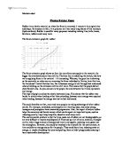
A black body is one that emits all possible wavelengths for its temperature (perfect emitter). A theory to predict how the intensity of EM radiation from a black body varied with wavelength. It worked for very short wavelength radiations but for those with short wavelength (I.e. ultraviolet), the intensity becomes infinite.
In practice, intensity rises to a maximum and falls again at short wavelengths. Position of the peak in the graph depends on the temperature of the body. The failure to predict the intensity was called the ultraviolet catastrophe.
Electron oscillation in hot bodies can only take certain discrete value (a quantum) of photon energy.
The photoelectric effect is the emission of electrons from a metal surface when an EM wave is incident upon it. The zinc plate of a gold leaf electroscope is given a negative charge, causing the leaf to rise (due to like charge repulsion). When UV light is incident on it, the leaf would fall - so it’s losing its negative charge, hence electrons are being lost. Other observations include:
- If a glass plate is inserted between UV light & zinc plate, electron emission ceases. Since glass plates absorbs the high energy UV photons and only the low energy (visible) photons are allowed to pass through.
- If an ordinary filament lamp is used (no UV light), there’s no discharge at electroscope. Even if the light is intense, no electrons are emitted - this is because the visible light photons are below the work functions of zinc.
Although lots of low energy photons in intense light, however each one of the photons are incapable of liberating an electron.
- Even if the UV radiation is very weak, discharge still begins immediately. Although there are very few UV photons, each one is still able to remove an electron - as they are either equal or above the work function of zinc.
Only quantized energy can be transferred in EM radiation. A quantum of EM radiation is called a photon.
Energy of photon = hf Where h = Planck’s constant (6.63 x 10⁻³⁴ Js)
For EM radiations: c = f λ so, f = therefore, Energy of photon =
To remove an electron from a metal atom, a minimum amount of energy is required, this is called the work function (φ). The energy required to liberate an electron must be delivered at once (cannot be stored up).
hf < φ, photon has insufficient energy to liberate an electron.
hf = φ, Electron can just leave the surface, f = f0 -threshold frequency (minimum frequency that is required to liberate an electron)
hf > φ, There’s extra energy after the liberation of electron, this become kinetic energy of electron.
Rearranging Einstein’s photoelectric equation:
hf = φ + Ek(max) into Ek(max) = hf - p
X-intercept = threshold frequency
Y-intercept = - φ
Work function is small energies with units of electron-volt (eV). This is the energy gained by an electron accelerate thorough a potential difference of 1 volt.
1 eV = 1.6 x 10⁻¹⁹ J (E = VQ <- charge of electron is 1.6 x 10⁻¹⁹)
φ of zinc is 4.3 = 4.3 x (1.6 x 10-19 J) = 6.9 X 10⁻¹⁹ J
According to wave theory, weak radiation should lead to electron being liberated after a sufficient amount of energy is gained after a long time - since energy would arrive continually at the zinc plate as a wave. However in reality provided frequency is high enough, electron emission occurs almost instantly.
UV light = 1 watt
Distance between UV light and zinc plate = 0.5 m
Cross section of zinc atom = 7.5 x 10⁻¹⁹ m2
Energy per second per meter square: ===> = 0.32 J
Energy per second overall: 0.32 x (7.5 x 10-19) = 2.4 x 10⁻¹⁹
Therefore, time taken for energy wave equal to φ to fall on cross sections:
= 2.9 s
There is no such delay in the emission of electrons.
Light is said to show wave - particle duality. In wave theory, energy is proportional to the square of the amplitude (E ∝ A2) - this is the intensity of the wave. So in Young’s experiment, the wave property of light is used to predict the amplitude of the wave arriving at a point on the screen.
Energy arriving per second is related to the E ∝ A2, as this can only be detected as photons, A2 is proportional to the number / chance of photon arriving at a point per second. So if there are lots of photon, more is detected here amplitude is greatest.