internal resistance.
ⅲ)Terminal voltage ≠ e.m.f of the power supply
p.d. across point A is equal to p.d. across point B
p.d. across point C is equal to p.d. across point D
We can say that point A & B have same p.d. and point C&D also have same p.d.
From the above Figure , we can see that
E = v + i r - - - - - - - - - - - - (1 )
As we all know, the load resistor draw most of the voltage( ∵ V α R )
so, we can say that VR = V
By equation ( 1 ) ,
V = E – i r
V= - i r + E
We can plot a graph that is V against I (terminal voltage against current)
By using Mathematical knowledge y = mx + c
We can see that Slope of the graph is equal to “ – r ”
so , the internal resistance ( r ) is equal to “- slope ”
We can derive the above experiment into two cases.
By V = E – i r
Case 1
when i = 0
(ⅰ) terminal voltage = e.m.f. of the power supply.
(ⅱ) power supply is in open circuit
Case 2
R = 0 , terminal voltage , V = 0
(ⅰ) terminal voltage = 0 V
(ⅱ) the power supply is in short circuit
(ⅲ) the maximum possible current , imax = E / r
(ⅳ) the power supply’s entire energy output is being wasted internally as heat .
We also can develop E = v + i r into
iE = iV + i² r
power supplied power delivered to power dissipated
by a cell external circuit inside battery
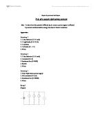
Procedure
(set up 1)
(1) Using wires to connect all the apparatus
(2) Connect 3 Light bulbs & a voltmeter in parallel
(3) Each circuit should contain one light bulb and one switch
(4) Switch on the switch one by one
(5) Notice the different shows on the voltmeter
(6) drop down the reading.
Results and Measurements (set up 1)
Tabulate the results as follows
e.m.f of the system (ε) = 2.50 ± 0.05 V
Experimental Data (set up 1)
Calculation (set up 1)
by V = I R , we have
Procedure
(set up 2)
(1) Using wires to connect all the apparatus in series
(2) Set the resistance to 20.0 Ω(initial value)
(3) Switch it on
(4) drop down the reading shows on the ammeter
(5) Turn to a larger resistance
(6) check out the different shows on ammeter and drop down the reading
Repeat step (5) & (6) to get more data .
Results and Measurements (set up 2)
Tabulate the results as follows
e.m.f of the system (ε) = 3.00 ± 0.05 V
Experimental Data (set up 2)
Calculation (set up 2)
by V = I R , we have
Procedure
(set up 3)
(1) Using wires to connect all the apparatus in series ( & earthing)
(2) Set the resistance to 10Ω
(3) Switch it on
(4) drop down the reading shows on the milliammeter
(5) Turn to a smaller resistance
(6) check out the different shows on ammeter and drop down the reading
Repeat step (5) & (6) to get more data .
Results and Measurements (set up 3)
Tabulate the results as follows
e.m.f of the system (ε) = 3.00 ± 0.05 kV
Experimental Data (set up 3)
Discussion
Q1 : Account for the causes of internal resistance in a power supply.
A : The causes of internal resistance in a chemical cell comes from the inherent resistance in the electrolyte. The internal resistance of an EHT is due to resistance of internal components such as transformer winding, rectifiers and transistors.Sometimes a resistor might be built in to limit the output current for protection purposes.
Q2 : We have assumed the resistance of the ammeter in the experiment to be negligiblty small. Is such an assumption justified ?
A: The resistance of the ammeter is negligible compared to the internal resistance of the EHT. However,it is not negligible compared to the internal resistance of the dry battery. It is because the resistance of the ammeter is near to the internal resistance of the dry battery.
Conclusion
From the above experiments , we can see that there is energy loss due to the internal resistance of the power supply (dry batteries) . This condition suits the equation
E = V + i r
( E = e.m.f. of the system,V = terminal voltage, i = current , r = internal resistance of the power supply )
Reference
Further Physics , Book 3 ; Third Edition ; Peter Fung , Peter Sun , Kenneth Young ; Longman Publishing Limited
Current Electricity , Dr.Ken Chan , P.43 – 44 , Wood Fire Publishing Co.