Characteristics of Ohmic and Non Ohmic Conductors.
Physics Coursework Characteristics of Ohmic and Non Ohmic Conductors Every part of matter is made up of atoms. Atoms are called the building blocks of nature. These atoms consist of a nucleus and shells. The protons and neutrons are part of the nucleus and the electrons are distributed in shells around the nucleus. The protons have a positive charge, neutrons are not charged and the electrons are negatively charged. Electrons have no overall mass while neutrons and protons both have a mass of 1 unit. This is how the relative atomic mass is calculated, by adding up the number of protons and neutrons. The electrons are distributed in the shell in order of the amount of energy that they hold. So according to that I will introduce the concept of electricity. Electricity is a flow of electrons. Electricity can be transferred by some materials and some cannot transfer it. Conductors are any materials or substances that can allow heat or electricity to pass through them. Conduction means that heat or current is transferred from atom to atom on its way out. Some materials are good conductors; some are bad conductors while some do not conduct at all. Such materials or substances that do not allow heat or current to pass through are called insulators. These insulators usually do not have enough electrons to carry the current and thus they are non-conducting substances. One example

Charging a capacitor at a constant rate
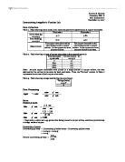
Lam Cheuk Ying Regina F.6C (12) Date: 25th March, 2010 Title: Charging a capacitor at a constant rate Objective: To investigate how the charge on a capacitor is related to p.d. applied across it by charging the capacitor at a constant rate. Apparatus: - capacitor (electrolytic type) 500 µF - microammeter 100k? - potentiometer 100k? - clip component holder - stop-watch - CRO - Connecting leads Procedure: (1) The circuit was connected up as shown above. The CRO was set to d.c. and the sensitivity was set to 1 V/cm. (2) The time base was set to any high value so that a steady horizontal trace is displaced. The trace was set to the bottom of the screen. (3) The capacitor was shorted out by connecting a lead across it and the 100k? potentiometer was adjusted for a suitable current, say, 80µA. (4) The shorting lead was removed and the capacitor would up charged up. Note what happened to the microammeter reading and the CRO trace. (5) The procedure was repeated but this time the stop-watch was started and the potentiometer was adjusted continuously to keep the current constant as the capacitor charged up. (6) The times for the CRO trace to move up by 1 cm, 2 cm, 3 cm, etc was measured. These were the times for the p.d. across the capacitor to reach 1 V, 2 V, 3 V, etc. (7) The results were tabulated. Precautions: The resistance R must be large so that the

Magnetic fields around electric currents
School: Class: Name: ( ) Subject: AL Practical Physics Date: Mark: C16 Magnetic fields around electric currents I-straight wire (TAS) Objective: To use a search coil and CRO to investigate the magnetic field due to a straight wire carrying an a.c.. Theory: In this experiment, a search coil is used to measure strength of magnetic field.For a long straight wire carrying current I ,there will be a magnetic field induced around the wire, given by . Results and discussion 7 Why is this necessary to ensure the search coil is at the same level as the wire? If there is inclination between the search coil and the wire, there will be a component of the magnetic field formed. The horizontal component of the magnetic field will be measured. This is not the maximum magnetic field that we want. 8 Why the sensitivity of the search coil can be increased by increasing the frequency? The more frequent the voltage across the wire, the more frequent is the change of the magnetic field. The magnetic field across the search coil is proportional to the sensitivity. 9 Tabulate the length l of vertical trace on CRO and current I measured in the table below: Length of vertical trace on CRO l/cm .2 2 3.4 4.6 6.2 7.6 8 Current I/A 0.1 0.2 0.3 0.4 0.5 0.6 0.7 0 Plot a graph of l against I. 1 The length of the vertical trace is directly proportional to
Current and Resistance Physics Investigation.
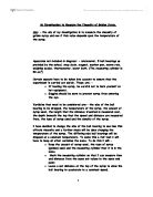
Current and Resistance Physics Investigation Aim: Investigate how the length of a wire affects the current and resistance of a wire. Prediction and Hypothesis: I think as you increase the length of the Constatan wire, you also increase the amount of resistance. The current is the flow of electrons; the current is dependent on the amount of voltage, which is applied. Voltage is the push given to the current. The current has to go through a circuit, which contains resistance so if you increase that push you also increase the flow of the current. All materials have a slight resistance to electricity factors affecting the resistance are: Length, Voltage & Temperature and Surface Area Voltage & Temperature Temperature has an affect on the experiment as the voltage has control over the temperature. The more the temperature increases the more the particles vibrate leading to a reduction in output voltage although not by a huge amount this does have an affect. Density Density has a large affect on the amount of resistance. The resistance depends upon the amount of denseness e.g. a large surface area has less resistance because a small area has tightly packed atoms which in turn rebound many of these electrons. Apparatus: · Power Pack · Constatan wire · Leads · Voltmeter · Ammeter Method: . Arrange apparatus as shown in the

Physics Case Study Solar Electric Panels
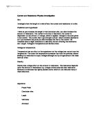
Physics Case Study – Solar Electric Panels The case study is the physics of solar electric panels and how they work. I am going to discuss the process in which these panels operate and their implications to society and their benefits and risks. The physics of solar panel cells How light interacts with the solar cells When light hits a solar panel, the solar panel material can reflect, transmit or absorb the light. When light does the latter of the three options, energy is transferred from the photons that make up light into the atoms of the material. If the energy of the photon, determined by the frequency, is higher than a specific level, it will cause an electron-hole pair. The process is known as the photoelectric effect. The specific energy level that is required signifies the ‘band gap’ between the valence and the conduction band. These bands are ranges of energy levels in which electrons rest at when under no excitation. When a photon has a higher energy level than the band gap hits an electron, it will excite it to the conduction band. In this band, electrons have enough energy to dissociate from its original atom and form free electron gas. Each material will have different bands and band gaps, and some don’t even have a band gap. The process of creating an electron-hole pair is most notable in semiconductors as a band gap exists, but is also relatively

Energy Efficiency Experiments
Experiments Method-Experiment 1 Firstly we put a light bulb into water which was about 150ml and let a current through to the light bulb. We measured the current, voltage, start temperature, final temperature and the time taken to get a temperature change of 10°C. Experiment 1- light bulb Data Start Temperature (°C) 22 Final Temperature (°C) 32 Voltage (V) 2.07 Current (A) 7.24 Time (S) 262 Mass(g) 0.15 Energy input = 7.24 x 2.07 x 262 = 3926J Energy Input= Current x Voltage x Time Energy output = 0.15 x 4.187 x 10 = 6.2805J Useful energy output= Mass x Specific heat capacity x Temperature change Wasted energy output = 3926 - 6.2805 = 3919J Wasted energy output= Energy input – Useful Energy output Energy → Light energy + Heat energy Efficiency = 6.2805 ÷ 3926 x 100 = 0.16% Efficiency=Useful energy output ÷ Energy input C:\Users\Hello\Pictures\TPhoto_00006.jpg Useful energy→ light Wasted energy→ heat Input energy→ electricity Output energy→ light+ heat Electrical energy→ light+ heat Method-Experiment 2 In this experiment we ran a current through an aluminium block and recorded the temperature change of 10°C. The procedure was the same as experiment 1 as it used an immersion heater to heat up the aluminium block and then record its mass. Experiment 2- Aluminium Block Data Start

investigating the relationship between the diameter and the current in a wire at its melting point
Investigation Report Aim - Theory - When current is passed through a wire resistance is created. This resistance is depends on the resistivity of the wire, current, voltage, wire length and cross-sectional area. So... R = ? . l A R = Resistance. P = Resistivity. L = Length. A = Cross sectional area. (Pg. 200, Accessible Physics, 1995, MacMillan Press ,ISBN 0333-627-80-6) (Pg. 47, Advanced Physics Revision Handbook, 1996, Oxford University Press, ISBN 0-19-914640-3) Looking for a formula for resistance - R = ? . l ( Resistance is the product of resistivity and length A per unit cross sectional area.) R = Resistance. P = Resistivity. L = Length. A = Cross sectional area. (http://physics.bu.edu/~duffy/PY106/Resistance.html) Looking for a formula for voltage - V = I . R (Voltage is the product of current and resistance) V = Voltage I = Current R = Resistance (http://www.allaboutcircuits.com/vol_1/chpt_2/1.html) Looking for a formula for Cross sectional area - A = ?r2 (Cross sectional area is the product of pie and radius squared) Or. A = ? 2 ( Cross sectional area is the product of pie and diameter per unit 2 all squared) A = Cross sectional area ? = Pie D = Diameter (http://www.equationsheet.com/sheets/Equations-20.html) So putting these formula together- A = ? 2
Investigating The Resistance Of A Light Bulb As The Voltage Is Increased.
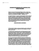
Investigating The Resistance Of A Light Bulb As The Voltage Is Increased. Resistance is the resist of electrons flowing through an electrical component. The resistance slows down flow meaning that the components will heat up due to friction. The current in a circuit gets smaller the bigger the resistance is. To work out resistance you can use this formula Resistance = Volts/Current, R=V/I To measure the resistance in a circuit you would need to find out what the voltage and the current is in the circuit. To find the voltage of an light bulb in a series circuit and hence the voltage of the circuit you would need to use a voltmeter which would be connect parallel with the light bulb to find the voltage across the bulb (see diagram below). Then you would need to find the current in the series circuit by placing an ammeter in the circuit which would give you the current of the circuit as well as the bulb current (see diagram below) Now you would then divide the volts by the amperes to find the resistance. Voltmeter and Ammeter in a circuit diagram For this experiment I would use a series circuit rather than a parallel circuit due to you only need to test the resistance of a light bulb once rather testing three or four light bulbs in a parallel circuit. To make the test safe I would make sure that I would work away from water, make sure my hands were dry and not sweaty as
Resistance Investigation
Introduction In this investigation I will attempt to find the relationship between voltage and resistance in a bulb using the equation: Resistance= Voltage/Current. Resistance: Resistance is the force that acts against charged electrons as they attempt to make their way around a circuit. More resistance means that more energy is needed to push the same number of electrons around the circuit. Many factors determine the resistance of an object for from its length or its temperature. Resistance is measured in ohms (?). The formula for resistance is: R=V/I Voltage is the driving force of electrons; to measure voltage is to measure the potential difference of energy between the positive and negative terminals. Voltage is a measure of the amount of energy that you are providing per coulomb of charge therefore 1vote = 1 joule per coulomb*. Voltage is measured in Volts (V) The formula for voltage is: V= IR Current: The current of a circuit is the rate at which the electrons flow through it. Current is measured in amps. The formula for finding current is I = Q/T where 'Q' is the charge passing at a certain point in the circuit measured in coulombs. Current is measured in amperes (A). Plan To do this I will carry out an experiment in which I will construct a bulb circuit with a voltmeter and an ammeter. Then, by passing a varying voltage across the bulb I will

Resistance Investigation
Physics coursework Hypothesis-I predict that the resistance of the resistors can be found by dividing the voltage by the current through the resistor. It can be found by finding the gradient of the best-fit line on the graph of voltage against current. This will happen because the voltage and current are proportional so voltage will equal constant current. The constant term is the resistance so the resistance is voltage divided by current. The gradient on the graph can be formed by dividing the unit on the y-axis by the unit on the x-axis which will be voltage divided by current or on the filament lamp graph it will be current divided by voltage. The gradient will depend on the resistance of the resistors. Ohm's law will be followed if the graph is a straight line through the origin, so this can be used to prove Ohm's law is valid. Background Information- Current is the flow of charge. Current is measured in ammeters which is the flow of electrons E.g. this is like a racing track the more cars on the track the more charge. Voltage is the energy each electron gets. A battery pushes electrons round the circuit. The size of the push is the potential difference produced by the battery and is measured in volts. A battery supplies energy to the rest of the circuit (chemical energy › electrical energy in the wires › light and heat energy in a lamp bulb). The potential