Stretching Springs/Hookes Law.
Mustafa Rafik 0.7Api Science coursework Title: Stretching Springs/Hookes Law Mr Bhatwadekar Scientific knowledge A force is able to change the shape of an object, the more the strength and force you apply, the more the shape of the object will change because the particles of the object are being moved therefore it will change the shape of the object because of the particles being pushed for e.g. A force is also able to change the motion of the object. The force, which is applied to the object, makes the object stay in that shape which is the cause of the force hitting the object and making it change, this will not go back to its original shape like shown in number 2, this is because the particles have been hit so hard that the attraction of the particles which makes them go back to its original shape have been damaged so it will then go into another shape. Elastic material This is a material that will stretch and go back to normal, its original shape. Elastics behavior is the ability of a solid to regain its shape when the external forces are removed. What is Hookes Law? Hokes Law is a rule for a spring, 'For a spring-that for a helical spring or other elastic material the extension is directly proportional to the applied force provided the elastic limit is not exceeded' This means that the extension is directly proportional to its force until its elastic
In this experiment we are investigating the effect of concentration on the current flowing through a copper sulpahte solution.
GCSE PHYSICS COURSEWORK In this experiment we are investigating the effect of concentration on the current flowing through a copper sulpahte solution. Prediction I think that the higher the concentration the higher the current passing through the solution, I also think that the higher the voltage, the higher the current. I think this will happen because there will be more copper sulphate molecules. Since there are more copper sulphate molecules, then there will be more sulphate ions giving up electrons to the anode (positive electrode) and more copper ions receiving electrons from the cathode, this means that there will be more electrons being transferred and so a higher current. The ions will break their ionic bonds because the copper plates are given a larger positive and negative charge by the battery (the circuit) and so the small force holding the ions together will be overpowered by the larger force of the electrodes on the ions. The liquid medium allows the ions to move freely and is what allows all of this to happen (The molecules in a liquid are more spaced out than in a solid (molecules in a solid bunched close together, with only enough room and energy to vibrate) and so this gives the ions the space and ability to move around and to actually get to the electrodes). To explain, ions are atoms that have gained or lost electrons to gain a charge. Copper gave up
To find the factors that affect the amount of E.M.F. being produced. The amount of E.M.F. produced during the experiment when each type of factors is change.
To find the factors that affect the amount of E.M.F. being produced. The amount of E.M.F. produced during the experiment when each type of factors is change. Planning Aim To find the factors that affect the amount of E.M.F. being produced. The amount of E.M.F. produced during the experiment when each type of factors is change. Background knowledge Electro-motive-force is the energy being supply to a charge. Battery is a type of energy. The energy that it provides is voltage. Battery voltage is sometime called electro-motive-force because it is used to "pump" around the electrons in the wire. The force can be generates by the moving of magnetic field as in the left-hand rules (field, current and force). It is the force that pushes the electrons around the circuit from the positive pole to the negative pole. That is why current directions in circuits are always marked from positive to negative. The voltage of the batteries varies in many volts e.g. 1.5V, 6V etc. A battery with a voltage of on volt is able to deliver one joule of energy for each coulomb of charge that passes through it. In other words, the voltage of a battery is the number of joules per coulomb that the battery can deliver when it is connected in a circuit. The law of left-hand rules or Fleming rules is that: * Thumb is for Motion. * First finger is for Field. * Second finger is for Current.

Investigation based on Hooke's law.
Background Information. This investigation will be based on Hooke's law. Robert Hooke was born in 1635, he was well known for his studies of elasticity. Hooke's most important discovery is the correct formulation of the theory of elasticity. An object is said to behave elastically when equal increases in the force applied to it produce equal changes in length. If a graph is drawn to show the average extension plotted against the load in Newtons a positive straight-line gradient should be seen, as extension is directly proportional to the load. The ratio between the load and the extension gives us a constant, this constant is called the spring or force constant. Hooke's law states: F = kx k = the constant of proportionality (the spring constant). x = the spring extension (e.g. x metres) Or: The deformation of a material is proportional to the force applied to it provided the elastic limit is not exceeded. The elastic limit is when the spring is permanently stretched on deformed, so it doesn't return to its original shape, as the molecules in the metal of the spring cannot return to the original shape; as the following graph demonstrates. Elasticity can also be shown in this simple diagram: The Molecular Level Description. Before. After. Combinations of springs. Hypothesis. ) I think that the stretch of the two springs in series will be double the stretch of
An Investigation into the Resistance of a Thermistor
An Investigation into the Resistance of a Thermistor Aim: Our aim is to investigate the temperature dependence of a thermistor, by heating it and measuring the current passing through it. We will collect three different pieces of data throughout the experiment, current, voltage and temperature. From this we will work out the resistance. Hypothesis: I predict that as we heat up the thermistor more current will pass through it. However the resistance of the circuit depends on the type of thermistor that we used (NTC or PTC). From looking ahead at the results our resistance decreased so this is a clear indication that we were using a Negative Temperature Coefficient thermal resistor and not a PTC, which would have increased resistance. So I predict that as heat enters the thermistor the electrons subsequently can move around and become free, the current will then increase as the electrons flow around the circuit and the resistance will decrease as more energy is supplied to it. The Voltage should not increase or decrease by more than 0.2V and I expect that the current will increase proportionally until the experiments end. Theory: My theory is that as we give energy the electrons can move around more and flow around the circuit. There is also a silicon semiconductor in the thermistor, which determines the amount of current to pass through the circuit. Method: Once you
Given a Tube Containing a Lens, Calculate The Focal Length of The Lens and Where The Lens Lies Within The Tube.
Given a Tube Containing a Lens, Calculate The Focal Length of The Lens and Where The Lens Lies Within The Tube. Plan I plan to set up the apparatus as shown below and change 'b'. To then make the image focus, I will have to change 'c'. When the image is focused, I will measure 'c' and also the magnification of the image. Using this information I will then be able to calculate 'a'. Hypothesis I predict that using the equations stated in the justification, after measuring values for 'c' and 'm'. I will be able to plot them on the graph of 'c' against 'm' Using the equation c = fm + [f - a]. I believe that if all the equations work, a straight line will be obtained. Safety After considering all aspects of this experiment, I have come to the conclusion that there are no significant safety issues. If normal levels of care are exercised, then there should be no risks involved. Variables that alter * b and c, (from diagram) * Magnification Variables to control * a (from diagram) * Ambient light * Part of object for which magnification is measured each time. * Place b is measured from and to Apparatus list * 0.15m tube * Lens * Object * 12V Power pack * Light source (lamp) white light average wavelength 550Nm * White screen * 2 x 1m rulers (0.0001m increments) * 0.15m ruler (0.0001m increments) * Stand and clamp * Spirit level Method
To build and calibrate a sensor in order to calculate the temperature of surroundings.
Using a thermistor as a temperature sensor AIM: To build and calibrate a sensor in order to calculate the temperature of surroundings. METHOD Firstly I assembled all of the apparatus shown in the diagram. I then heated some water in a kettle, and poured it the big beaker. Next I lowered the beaker containing the ethanol into the hot water, with the thermistor just below the surface of the ethanol. I took the voltmeter reading for every 5 degrees Celsius as the temperature of the ethanol rose. I then added ice to cool the water down, again taking readings as the temperature of the ethanol declined. I repeated this experiment three times and took averages for each of the temperatures recorded. FAIR TESTING To ensure the test was entirely fair, I made sure that the same thermistor was used for each experiment. I also used the same volume of ethanol to ensure this had no effect on the result. The same thermometer was also used for the same reason. The potential difference delivered around the circuit was kept to a constant three volts, and I used the same fixed resistor to ensure that the potential difference split evenly across the resistor and thermistor, which would have severely affected my results. SAFETY ASPECTS The main safety aspect to consider whilst doing this experiment involved the use of ethanol in the experiment, especially as I planned to heat it. As ethanol

Resistor - What do resistors do?
Resistor What do resistors do? Resistors limit current. In a typical application, a resistor is connected in series with an LED: Enough current flows to make the LED light up, but not so much that the LED is damaged. Later in this Chapter, you will find out how to calculate a suitable value for this resistor. (LEDs are described in detail in Chapter 5.) The 'box' symbol for a fixed resistor is popular in the UK and Europe. A 'zig-zag' symbol is used in America and Japan: Resistors are used with transducers to make sensor subsystems. Transducers are electronic components which convert energy from one form into another, where one of the forms of energy is electrical. A light dependent resistor, or LDR, is an example of an input transducer. Changes in the brightness of the light shining onto the surface of the LDR result in changes in its resistance. As will be explained later, an input transducer is most often connected along with a resistor to to make a circuit called a potential divider. In this case, the output of the potential divider will be a voltage signal which reflects changes in illumination. Microphones and switches are input transducers. Output transducers include loudspeakers, filament lamps and LEDs. Can you think of other examples of transducers of each type? In other circuits, resistors are used to direct current flow to particular parts of the circuit, or
Test of the reed switch capacitors in series and in parallel
School: Class Number: Name: Class: Date: 1th May, 2008 Mark: Title Test of the reed switch - capacitors in series and in parallel Objective - To use a reed switch to measure the capacitance of some real capacitors, including those of series and parallel combinations - To investigate how the reed switch current varies with the frequency Apparatus Reed switch x1 Signal generator x1 Resistance substitution box x1 Battery box with 4 cells x1 Milliammeter x1 Voltmeter x1 Capacitors C1 and C2 Connecting wires Theory Reed switch current In the experiment, the reed switch allows the capacitor to be charged up and discharged rapidly. If a capacitor with capacitance C is charged up at a voltage V, the charge Q stored in it will be equal to CV. If the frequency f is operated by the reed switch, the charging up and discharging process will be repeated f times per second, the charge Q in the capacitor will be delivered to the milliammeter at the same rate. Assuming the capacitor is fully charged and discharged every time, the total charge Q total passing through the milliammeter per second is equal CVf, which is the theoretical current I. And the capacitance of the capacitor can be estimated by the formula C = I/ Vf. Capacitors in parallel If capacitors C1, C2, ..., CN are connected in parallel, the charges stored in each capacitor are shown as
Science 1 Investigating thedeflection of a cantilever.
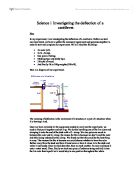
Science 1 Investigating the deflection of a cantilever. Plan In my experiment, I am investigating the deflection of a cantilever. Before we start our experiment, we have to gather the necessary equipment and apparatus together in order to start and complete our experiment. We will need the following:- * 1m ruler (x2). * 2x G- clamps. * One piece of string. * Masking tape and sticky tape. * 2 blocks of wood. * And finally 1k in 100g weights (100x10). Here is a diagram of our experiment. The meaning of deflection is the movement of a structure or a part of a structure when it is bearing a load. Once we have collected all the equipment needed to carry out the experiment, we need to first put it together and set it up. We do this by taking one of the 1m rulers and clamping it onto the end of the desk with a G- clamp. We also put some wood in-between the ruler and G- clamp, the reason for this is because we don't want the ruler and table being indented by the clamp. We found out that this could be the best thing to vary. The reasons for this is because we could choose whether to have the ruler further away from the desk and have it bend more or have it closer in to the desk and make it less bendy. Once we had done that, then we took another 1m ruler and taped it onto a retort stand. Then, finally we took one piece of ordinary string and tied it onto the 1m ruler