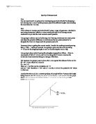
and mx = ½at² therefore x = ½t² and m = a so the x-axis will be plotted to ½t² where t is the time
I predict that there will be a constant gradient of around 9.81ms-² between the height being dropped and ½t² helping me prove “g” by freefall. I also predict that the graph should show a trend in the distance fallen +/- 0.1cm to ½t² due to the gradient remaining a constant.
My predicted graph for my result
Prior to my main experiment I did a preliminary experiment to see how many final test proved in the accuracy of “g” by freefall, as well as giving me an idea of what to expect for my results and help me in deciding what apparatus to use.
Apparatus:
- Stopwatch
- Ticker Timer
- Ruler
- Clamp
- Boss
- Retort Stand
As it’s a very simple experiment the set up of the circuit will be very simple too the ticker timer will be placed on a clamp attached to a retort stand and the ticker timer will have a weight attacked to a 5cm strip of paper and the ticket timer will punch holes in the paper every 0.02s as it falls, so all there is to do is count the dots for each height and times it by 0.02.
Results
Here are the averages of the results I got for the ticker tape experiment after I had all the data there I still had some work to do yet which was working out “g”
Apparatus:
- Retort Stand
- Timing Electronics
- Wires
- Boss
- Clamp
- Ball Release Mechanism
- Micro switch (Pressure Pad)
Diagram:
Method:
- Set up apparatus as show above so the ball releasing mechanism is directly above the micro switch and test the circuit to check that it works correctly
- Pull the micro switch up to reset it and then insert the ball bearing into the release mechanism.
- Set the height of the release mechanism to desired distance
- Release the ball bearing so that it strikes the pressure pad and record the time take to fall
- Repeat step 4 until you have a three similar results for that distance
- Then repeat step 3 onwards until all the heights have been completed and recorded
Safety:
I believe there is very little risk to this experiment as nothing is potentially a real danger for the user. The only main problem is the miss use of electrical equipment but as the voltage being used is quite minimal there’s very little chance of any sort of serious injury. So as long as the experiment is carried out properly and safely then nothing should be a problem.
Results:
Here are my results I got from the experiment, as you can see all three attempts have been averaged so that they can be used for the next stage of my results.
As I predicted there is a good correlation between the data ½t² taking into account room for air resistance and measuring error.
Analysis of results:
Firstly, the main conclusion I can make from looking over my results and graph is that there are slight factors effecting the results such as the uncertainty of +/- 0.1cm of the distance fallen as well as a slight effective of air resistance coming into play; although that’s so small it can be excluded for the time being.
As you can see from the graph I measured my gradient for 0.0483 on the x-axis and 47.5cm on the y axis giving me an answer of:
47.5
G = 0.0483 = 9.83ms-²
Although you also have to take into account the +/- 0.1cm distance fallen you can clearly see the range of error for “g” is:
47.4 47.5
G = 0.0483 ←→ 0.0483
Having g range from
G = 9.813 ←→ 9.855
As you can see taking into account +/- 0.1cm makes a real difference to the results helping you get a more clear view of what the possibilities so it is clear whether the test has had anomalies along the way.
Fitness For Purpose
As you can see from the analysis I was able to accurate plot “g” by freefall even more this proved that the system I used to find “g” in my experiment was well suited for the task in hand. I also thought that the task used relates well to everyday surroundings as gravity takes a big part.
From the experiments I did you can clearly see that the system I finally used to plot my analysis is well suited to the degree of accuracy needed for something like this. With a difference in the experiments using the ticker time and having “g” = and in my experiment involving the timing electronics where “g” = 9.83ms-²