The results from this experiment tell me that when the resistance is kept constant, the (V, I) graph drawn will have a positive gradient and be a straight line. This has helped me in my prediction. From the experiment, I have also learned of the necessity, to carry out repeated experiments. In the results above, I failed to do so, and that explains why the graph isn’t as straight as it should be.
Plan
For this experiment, I will have one independent variable. This is going to be the voltage. As the voltage of the circuit is going to vary, there will be at least two dependant variables. These are going to be the current flowing through the circuit, and for the bulb experiment, the brightness of the bulb, is also classified as a dependant variable.
I will investigate the relationship between the current and voltage, for a wire wound resistor, ad a light bulb, as well as the relationship between the resistance and % of light emitted by the bulb. As stated above, the only independent variable will be the potential difference off the circuit. This will be controlled using a potentiometer.
The resistance of the components will be a constant, except for the light bulb. As this will light up, the resistance will also vary.
As I predict the graph for the light bulb to be a curve, I will receive about 12 results for each different component. These will be carried out at suitable intervals, depending on the component. The experiment will be carried out three times to ensure that average readings can be obtained.
The experiment will be carried out fairly, s possible. Averages will be taken, from the 3 sets of results for each experiment, to ensure the results are true as possible.
The lux meter will be surrounded by cardboard, so that outside light is omitted. If a reading is evident on the luxmeter, I will just deduct it from the percentages recorded.
Prediction
As the voltage increases, by myself adjusting it using the potentiometer, the current flowing to the circuit will, also vary. If the voltage, increase, then I expect the current to also decrease, and visa versa. This is exactly the same a saying that V is directly proportional to I. As this is the case, I expect a graphs for both the " wire wound resistor," and the "light bulb," to have graphs with a positive gradient.
As the resistance, of the, " wire wound resistor," will be a constant, I expect a straight line graph. There I also expect the resistors to be applicable to ohms law. This is, as the temperature of the resistors will be kept constant, as the voltage will not be very high. For the light bulb, the resistance will vary and will never be constant. As this is the case, I expect a graph with a curve, and positive gradient. The graph will start to curve more, and have a steeper gradient the greater the voltage, and current are. This is due to the bulb resistance, starting to become more constant. As the temperature is not constant, I don´t not expect the light bulb to be applicable to Ohms law.
The relationship between the % of light, and the resistance, I believe would give an S shaped curve. I believe this, as no light will be given off, even though there is some resistance in the circuit. This is, as the bulb needs a certain amount of activation energy. Before it lights up. Once the bulb has been lit up, there will be a steep gradient for a while, and then the gradient will decrease. This is, as the resistance is not increasing at the same rate, even though the current and voltage will be. As this is the case, the graph will start to go horizontal.
Prediction graphs
Independent variable - Voltage
Dependant Variable - Current, Brightness of bulb, resistance ( only for the bulb experiment)
Apparatus
Wire wound resistors, 1 ohm & 2 ohm
Light bulb
6 Volt battery pack
Potentiometer
Red and black wires
Ammeter
Diagram
Voltmeter
For wire wound resistor
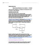
1) Set up circuit as shown in diagram
2) put the one of the resistor in the circuit. Check that the ammeter shows current in Amps and that the voltmeter shows a positive reading.
3) On the desired scale, carry out the experiment, recording the voltage, and current. Do this until you have acquired suitable results to plot a graph.
4) Once you have completed it once, repeat the experiment 2 more times, so that an average can be calculated.
5) Once the experiment has been carried out for the 1-ohm resistor, repeat the above procedure, with the 2-ohm resistor.
For the light bulb
1) Set up the circuit as shown in diagram.
2) Place the bulb at the back of the box, and attach the connections.
Put the luxmeter into the cardboard box, ensuring that its sensor is very close to the bulb each time round and that it is pointing towards the bulb.
3) Turn the luxmeter on, and record the % it shows. * Deduct this from the results you receive once, the circuit is in use.
4) Turn the potentiometer to the maximum, so that you can find out what the maximum pd. will be from this you can derive a suitable scale to go up in, so that you can acquire sufficient results to plot a graph.
5) On the desired scale, carry out the experiment, recording the voltage, and current. Do this until you have acquired suitable results to plot a graph.
6) Once you have completed the experiment once, repeat the experiment 2 more times, so that an average can be calculated.
Analysis:
For the wire-wound resistors, which were 1 ohm and 2-ohm resistors, the results proved a directly proportional relationship between the pd. and current, of the circuit. This was due to the fact of the resistance being kept constant, through out the readings. The graph for these were a straight line, with positive gradients which proved my prediction to be correct, see graph one (1 Ohm resistor) and graph two (2 Ohm resistor). This means that ohms law was applicable in this experiment.
From fig 1, it is evident, that ohms law is applicable. All the points lying on the best-fit line demonstrate this. The resistance, was first calculated by using ohms law, of V=IR, which was rearranged to R=V/I. As seen on the table of results, for 1 ohm resistor, the resistance received by using the formula, was 1.11 ohms. This is very close to 1 ohm, which was resistance of the resistor used. This provided sufficient evidence, to believe that the results I received were correct. By drawing a (V, I) graph, the resistance again can be derived, and be seen whether it matches the figure calculated using ohms law. The resistance was calculated, by using the gradient of the graph. This is because:
Y = m x X + c
V = R x X + 0
The resistance calculated, for the 1-ohm resistor, is slightly higher than the 1 Ohm, by 0.11 Ohms it should be. This could either be due to two factors. Either the resistor had a false resistance, or the current and voltage I results I used, were not totally accurate. I believe that the current readings were not accurate, as the ammeter fluctuated. The current readings were accounted in amps, when they should have been measured in Millie-amps, which would have given even more accurate results.
From fig 2, which was the results for the 2-Ohm resistor, it is evident, that like the 1-ohm resistor, there is a directly proportional relationship between pd. and current. This graph was also a straight-line graph, with a positive gradient, which means that the resistance was a constant. This means that ohms law is applicable, as it should be, as the temperature of the circuit was kept constant, was high voltages were not used. This set of results also proved my prediction to be correct, a straight-line graph with a positive gradient. By using ohm formula, V=IR, The resistance of the circuit was calculated to be resistance 2.08 Ohms. Too ensure that this was correct, the resistance was again calculated by calculating the gradient of the fig 2 (V, I) graph. (The same process used for the 1-ohm resistor, to calculate the gradient was used.). The gradient for this graph was also proved to be 2.08. This is exactly the same as the figure received, when the resistance was calculated using the V=IR, which was rearranged to R=V/I. The resistance received was not exactly 2 ohm, this was on both occasions when calculated. This is again, like the result for the 1-ohm resistor, was probably due to readings on the both the ammeter and voltmeter. I should have used Millie-amps to measure the current, as this would have given a more accurate reading.
From fig 3, it is evident that the 2-ohm resistor has a larger gradient than the 1-ohm resistor. This is correct and is what is expected. This is due to the resistance, being equal to the gradient of the graph, as proved earlier. The 2-ohm resistor has approximately double the gradient of the 1-ohm resistor.
The light bulb results produced a curved graph, as seen in fig 4. As this was the case, it dictates two things. The first is that the Ohms law is not applicable, as the temperature is not constant, and that the resistance of the bulb is not constant. This labels the light bulb being a non- Ohmic conductor. The graph proves my prediction, as the graph is curved and has a positive gradient. The graph also seems to curve more, and have a steeper gradient, the more the voltage and current ids increased. This was also what I predicted.
The gradient of the curve is very small at the beginning, meaning that there is low resistance. As the voltage and the current increase, the gradient of the curve also increase. This means that the resistance of the bulb is increasing, and that the resistance of the bulb is becoming more constant. As the temperature of the bulb is not kept constant, ohms law is not applicable. However it is still evident that as the current and voltage of the circuit increases, so does the resistance.
From fig 5, it is evident that the percentage of light given out is directly proportional to the resistance of the circuit.
The graph starts out very flat, and while there is a current and voltage in the circuit, there seems to be no percentage in light given out. This is, as the bulb needs a certain amount of energy before it can emit light. The graph begins to curve at the point when the resistance of the bulb is a 5.6 ohms. As the resistance increases, the percentage of light also increases. It increases sharply, from that point until about the when the resistance of the bulb is 12.5 ohms. From there on the percentage of light given out, is at a lot slower rate, while the current and voltage are still increasing. The percentage of light given out is not increasing at the same rate as it once did, as the resistance of the circuit, begins too become more constant. As it is the resistance of the bulb, which effects the percentage of light given out occurs at a slow rate. The bulbs resistance becomes more constant, as the bulb is at it’s brightest, as the filament is burning at its brightest, and can’t emit any more light. This is seen on the graph after the 12. 5 ohm point, which shows the graph becoming horizontal.
Evaluation:
This experiment was carried out extremely fairly. We had a suitable and very effective method, which managed me to receive sufficient fair results. I was also capable of repeating the experiment for each resistor 3 times, so that an average will be able to be calculated. The results we received were proved to be fair. This was done by most of them being exactly identical as when I repeated them. However there were a few results that weren’t identical to the other ones received.
E.g.
P.D (volts V) Current (amps I)
attempt 1 Attempt 2 Attempt 3 Average
2.75 0.20 0.20 0.19 0.20
3 0.21 0.21 0.20 0.21
3.25 0.21 0.21 0.21 0.21
3.5 0.22 0.22 0.21 0.22
3.75 0.23 0.22 0.22 0.22
The highlighted figures, aren’t identical, like the majority of the results I received. This is most probably due to human error. Even though this is the case, it in no means effects the graph and conclusion I have drawn up. These results are fairly constant, and are acceptable.
If was to do this experiment again, I would make some alterations to the method. First of all, I would use an ammeter, which measures in Millie-amps, as this would give a more accurate reading of the current. This is why I feel that when the calculations that were done for the conclusion, that the resistances received were not exactly 1 ohm and 2 ohms.
I would also use a more rigid, and opaque, box, to cover the luxmeter. This will there for allow the out side light to be 0 %, giving more accurate readings. The box I used, was not totally acceptable, as it may have had slits in it which could let light through, which could have effected our readings. If the box were also lined with black paper, it would be an improvement, as any light not from the bulb would be absorbed. We used a light coloured box, which would have effectively reflected light from out side around the box. The experiment could also be carried out in a dark room, so that there is absolutely no chance of light from out side effecting the readings on the luxmeter.