Single Phase Transformer (Experiment) Report.
Electrotechnology Coursework
Single Phase Transformer (Experiment) Report.
Aims.
The aims of this experiment are to calculate the turn's ratio of the transformer (in the open and short circuit test), calculate the inductive reactance and rm from the values in the open circuit test. In the short circuit test calculate R1 and X1. Then finally in the load test calculate voltage regulation and the efficiency compare these results to the voltage regulation and efficiency from the equivalent circuit. I will then predict the voltage regulation and efficiency if the load used above had a power factor of 0.8 lagging.
Objectives.
To determine the approximate equivalent circuit of a single-phase transformer. This will enable me to calculate all the different parameters in the open-and short- circuit tests. Enabling me to predict results for an actual circuit and also compare values between actual and equivalent circuits to see how accurate the estimation or prediction is.
Equipment.
TecQuipment electrical machines teaching unit NE8010 or NE8013, with the B-phase transformer (EMTU-TT01) on the bench. One feedback electronic wattmeter, one Multi-range moving-iron ammeter and one instrument voltage transformer. Electrical wires where used for the connections between the components of the circuits.
Theory and Introduction.
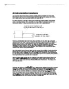
A Transformer is a device that transfers electric energy from one alternating-current circuit to one or more other circuits, either increasing (stepping up) or reducing (stepping down) the voltage. Transformers are employed for widely varying purposes; e.g. to reduce the voltage of conventional power circuits to operate low-voltage devices, such as doorbells and toy electric trains, and to raise the voltage from electric generators so that electric power can be transmitted over long distances. Transformers are widely used in power systems for the stepping up the generated voltage from about 20kV to 400kV for efficient transmission and then down again in stages (typically 132kV, 33kV and 11kV) for distribution to industrial consumers and finally to 230V for domestic purposes. Power system transformers are usually 3-phase devices, but their basic concepts are most easily demonstrated using a single-phase transformer.
Transformers change voltage through electromagnetic induction; i.e. as the magnetic lines of force (flux lines) build up and collapse with the changes in current passing through the primary coil, current is induced in another coil, called the secondary. The secondary voltage is calculated by multiplying the primary voltage by the ratio of the number of turns in the secondary coil to the number of turns in the primary coil, a quantity called the turns ratio. So transformers operate by mutual induction, with energy being transferred between two (or more) separate windings via a coupling magnetic field. Their performance can be modelled, predicted and analysed using equivalent circuits.
When a transformer is not connected to a load, the secondary coil does nothing. The primary coil nevertheless takes a small current, I0, made up of two components: the magnetising current which provides the useful flux linking the coils, Im, and the current supplying the power lost in the core, Il. I0 remains constant whether the transformer is loaded or not. Im lags Il by 90o, so the transformer's equivalent circuit must contain a core loss resistance, R0, in parallel with an inductive reactance, Xm, both in parallel with the primary winding. The primary and secondary coils each have small resistance, R1 and R2, in series with the windings, representing the coil resistance.
the single impedance Z1 comprises
* A primary circuit resistance R1, which is the sum of the primary and referred secondary winding resistances.
* A primary circuit reactance X1, which is the sum of the primary and referred secondary leakage reactances.
I0 is the no-load primary current, it comprises a reactive or magnetising component I0r, which produces the flux and an active or power component I0a, which supplies the losses and is in phase with V1.
The no-load current and power-factor are respectively
I0 = V(I0a)2 + (I0r)2 and cos ?0 = I0a
I0
The power factor is usually low on no-load because I0 >> I0a.
* I'2 is the component of the primary current which compensates for the secondary load current. I'2 = I2(N2/N1)
* I1 is the total primary current, the phasor sum I0 and I'2.
* I'2R1 is the voltage drop associated with the winding resistance and is in phase with I1.
* I'2X1 is the voltage drop associated with the total leakage reactance and is in phase quadrature with I1.
* Cos ?1 and cos ?2 are the primary and secondary power factors respectively.
* V2 = V'2(N2/N1)
Because the no-load current is relatively ...
This is a preview of the whole essay
* I'2 is the component of the primary current which compensates for the secondary load current. I'2 = I2(N2/N1)
* I1 is the total primary current, the phasor sum I0 and I'2.
* I'2R1 is the voltage drop associated with the winding resistance and is in phase with I1.
* I'2X1 is the voltage drop associated with the total leakage reactance and is in phase quadrature with I1.
* Cos ?1 and cos ?2 are the primary and secondary power factors respectively.
* V2 = V'2(N2/N1)
Because the no-load current is relatively small rm and xm are often neglected when considering the behaviour near full-load.
Expressions for both the voltage regulation and the efficiency can be derived from the approximate equivalent circuit.
Voltage regulation is the change in the secondary voltage between no-load and full-load. It is expressed as a fraction (either per-unit or per-cent) of the no-load voltage with the primary voltage with the primary voltage assumed constant.
Efficiency is the ratio of output power and input power. It can be expressed either in per-unit or per-centage terms.
Measurements.
Open-circuit test.
The actual circuit is shown in Appendix 2.
V1 /Volts
I0 /Amps
Poc /Watts
V2 /Volts
Deflection
Amp Range
Volt Range
80
0.042
2.4
40
0.24
0.1
00
00
0.049
3.5
50
0.35
0.1
00
20
0.056
4.6
59
0.23
0.1
200
40
0.064
6.2
69
0.31
0.1
200
60
0.073
7.6
79
0.38
0.1
200
80
0.084
9.4
89
0.47
0.1
200
200
0.098
1.0
99
0.22
0.1
500
220
0.117
3.0
09.5
0.13
0.2
500
240
0.141
6.0
19
0.16
0.2
500
260
0.173
8.0
29
0.18
0.2
500
Here is an equivalent circuit diagram for this test: -
Short-circuit test.
The actual circuit is shown in Appendix 3.
I2 = 6A
I1 = 2.97A
Vsc = 123/5 = 24.6V
Amp range = 5
Volt range = 50
Deflection = 0.12
Psc = 30 W
Here is an equivalent circuit diagram for this test: -
Load Test.
The actual circuit is shown in Appendix 4.
V1 = 230V
I1 = 0.131A
Switch
V1 /Volts
I1 /Amps
V2 /Volts
I2 /Amps
Deflection
Amp Range
Volt Range
Pin/ Watts
Off
231
0.131
15
0
0.14
0.2
500
4
Pos 1
231
2.74
10
5.5
0.255
5
500
637.5
Output Power = V2I2 = 110 x 5.5 = 605 W
Here is an equivalent circuit for the load test: -
Calculation of Equivalent Circuit Parameters.
Open-circuit test.
The graph of Primary current vs. Primary voltage is shown in Appendix 5, the second graph with Input power and Power lost against Primary Voltage is shown in Appendix 6, the results below are read directly from the graph and table above.
The rated primary voltage = 240 Volts.
The values for the following at this rated voltage are;
* Primary current = 0.141 Amperes
* Secondary voltage =
If the primary voltage is 240 Volts (the rated voltage) then I will use the turn's ratio formula to find the secondary voltage.
N1 = V1 = 2.02 = 240 Therefore V2 = 240 = 118.8 Volts.
N2 V2 V2 2.02
* Input power = 16.0 Watts
Turns-Ratio = N1 = V1 = 160 = 2.02
N2 V2 79
rm = V12 = 1602 = 3368.42
Poc 7.6
V1 160
Xm = = = 2886.40
V (Io)2 - (V1/rm)2 V 0.0732 - (160/3368.42)2
The lines on the graph involving the power loss and input power against the primary voltage are the same to one decimal place, which is not realistic. If power loss = power input then there would be no power output. If I look closely at the results worked out for the graph, say for 220V (the rated voltage), gives 13.00000 Watts for the input power, where for power loss the value is 12.99999. This shows that there is a small amount of power which is not lost; this power is then amplified at the secondary coil.
Input Power /W
Power loss /W
3
2.99999
Short-circuit test.
R1 = Psc = 30 = 3.40?
I12 2.972
X1 = (Vsc)2 - R12 = 13.86
V ( I1 )
Load Test
Voltage regulation = V2(no load) - V2(loaded) [x 100%] =
V2(no load)
15-110 [x100%] = 4.35%
115
Efficiency = output power = V2 I2 [x 100%] = 110 x 5.5 [x 100%]
Input power Pin 637.5
Efficiency = 94.9%
Calculation of the Voltage regulation and Efficiency for the load test using the Equivalent circuit parameters.
(In these calculations the equivalent circuit parameters calculated and listed above are used, ? in these calculations will be considered as being zero)
Voltage regulation = I'2 (R1 cos ?2 + X1 sin ?2) [x 100%]
V1
= 2.72 (3.4) [x 100%] = 4.00%
231
Efficiency = V2 I2 cos ?2 [x 100%] =
V2 I2 cos ?2 + V12/rm + I'22 R1
Efficiency = 110 x 5.5 [x 100%] =
110 x 5.5 + (2312/ 3368.42) + 2.72 x 3.4
Efficiency = 96.0%
Comparison between the load test and the voltage regulation calculations.
I worked out the voltage regulation and the efficiency of the load test in 2 different ways, firstly I used the method where I use to values from the actual experiment and use them in the formulae above. The second method was where I used the equivalent circuit parameters calculated to using the results from the open and short circuit tests, and then used these in the formulae to calculate the voltage regulation and the efficiency.
My results show that when I calculate the voltage regulation with the experiment values (actual circuit), the change in the secondary voltage between no-load and full-load is 4.35%. This value is 0.35% greater than the value calculated using the equivalent circuit parameters. So therefore the voltage regulation calculated with the equivalent circuit formula is 4.00%.
The Efficiency values are the other way around. For the experiment values used in the efficiency equation, the efficiency value is 94.9%. This value is less than the efficiency value produced when the equivalent circuit parameters are used in the equation. This value is 96.0%.
My values are very close to the correct trend from my knowledge. With the circuit not being exactly perfect due to losses, such as power losses due to heating in the wires around the circuit. There are also eddy currents and hysteresis within the core of the transformer. All these losses add up to alter the efficiency of the circuit. With the calculations from the actual circuit the efficiency was calculated and it was lower then the efficiency calculated using the equivalent circuit formula. I can see that the actual circuit formula takes all the losses into account, due to the value of the voltage recorded is used in the formula. With the equivalent circuit parameters being only estimation, this leaves with the opinion of it being less accurate, with also the knowledge of the formula not taking into account the heat losses and power losses in the wire, which is bound to affect the efficiency of the circuit performance.
The voltage regulation difference shows that in the equivalent circuit the change from voltage with no load to voltage with a load has a smaller change (smaller percentage) therefore the circuit is more efficient. So with the actual having a larger change (larger percentage) then the efficiency will be less.
Areas of Application of Transformers.
The control of transformer ratio under load is a desirable means of regulating the voltage of high-voltage feeders and of primary networks. It may be used for the control of the bus voltage in large distributing substations. It finds a wide field of application in controlling the ratio on step-up transformers operating from power stations whose bus voltage must be varied to suit local distribution.
In industrial work, it is used for the control of current in a variety of furnace operations and electrolytic processes. It all furnishes a convenient means for voltage regulation of concentrated industrial loads.
Power transformers are for use in connection with a.c. power supplies are chiefly characterized by a constant primary voltage and a single frequency. These are used for power distribution, particularly in aircraft.
A wide-band transformer is one which has to work well over a wide range of frequencies. The most common example is the audio-frequency transformer for transmitting speech and music; there are also applications in the supersonic range.
Television scanning transformers have a close analogy with the current transformer; they are used to handle the special current-waveforms which produce the 'raster' or rectangle of parallel lines on the screen of a television receiver. Each line is a result of a rapid horizontal movement of the cathode-ray spot. A slower vertical movement of the spot causes the repeated horizontal movements to build up the raster. The deflections of the cathode-ray beam are usually brought about by two pairs of magnetic deflecting coils carrying currents of saw-tooth waveform. These currents may be produced in a number of different ways, but a common method is to pass the anode current of a pentode through the primary winding of the scanning transformer with its secondary closed by a pair of deflecting coils. A saw-tooth voltage applied to the grid, of the pentode produces the desired deflections of the spot.
The widespread use of radar in World war two involved the development of transformers capable of supplying electrical energy in brief, intense pulses to the radio transmitting valves. The pulse technique finds numerous applications outside the field of radar. In electrical measurements of all kinds when the continuous application of voltage is not allowable, because of over-heating or for other reasons, the use of pulses offers a solution.
Discussion with ECP and experiment.
Equivalent Circuits are used throughout transformer businesses to predict the voltage regulation and efficiency incase of problems in circuit, consistency in a circuit or maybe boosts at predicted times like in T.V viewing when there is something very popular being viewed, a lot more people watch T.V and watch a specific channel. In this experiment I have used the equivalent circuit formulae to check and compare with the actual values. In a simplified equivalent circuit shown in the theory section would give a voltage regulation around 3-5 per cent. The values I calculated were 4.00% and 4.35% which are within the ideal values. Due to the ability of equivalent circuit prediction your able to predict the value of voltage and current say for houses or factories, because if you don't have enough voltage then nothing will work, but if you have too much then you will blow the accessories. So it is very helpful being able to predict and estimate fairly accurately.
The efficiency calculations where reasonable in the way that the transformers where efficient and that they followed the trend of the voltage regulation, where the higher the voltage regulation the less efficient the circuit was.
The calculations have proved to me that the equivalent circuit method has worked, enabling me to predict the results of a transformer and effects with certain loads.
* Now to predict the voltage regulation and efficiency if the load used above had a power factor of 0.8 lagging.
(So now instead of the ? being a value of zero, the cos ? now becomes the value 0.8 therefore the value for sin ? is 0.6,and due to it lagging then in the voltage regulation equation the sign in the middle must be an add and not a minus.)
Firstly I had to calculate the primary current which compensates for the secondary load current (I'2).
Using the formula I'2 = I2 (N2/N1) = 2.72
Voltage regulation = I'2 (R1 cos ?2 + X1 sin ?2) [x 100%]
V1
= 2.72 (3.4 x 0.8 + 13.86 x 0.6) [x 100%] = 13.0%
231
Efficiency = V2 I2 cos ?2 [x 100%] =
V2 I2 cos ?2 + V12/rm + I'22 R1
Efficiency = 110 x 5.5 x 0.8 [x 100%] =
110 x 5.5 x 0.8 + (2312/ 3368.42) + 2.72 x 3.4
Efficiency = 95.1%
Voltage regulation goes up a lot due to the load being 0.8 lagging. Now it is 0.8 lagging, and therefore cos ? = 0.8, so therefore sin ? = 0.6. This then involves X1 into the equation, which is the leakage reactance. The leakage flux largely determines how good the transformer is at maintaining its voltage load, so it is essential to minimise it. With the load being added, the transformers effectiveness decreases and produces more leakage flux, therefore producing a bigger difference between the voltage without load and the voltage with load. To reduce the voltage regulation value the following can be done: -
* Wind primary and secondary over each other - interleaving the layers helps further.
* Sandwich the coils.
* Make the coils longer and thinner by making the limbs longer and the yoke shorter.
* Use a core which completely encloses the winding.
With the primary wound around one limb and the secondary coil wound on another limb, as its excessive leakage flux would lead to very poor regulation.
Looking at the results, I can say that they look realistic, with the efficiency obviously decreasing due to the losses in the transformer with the leakage flux and also around the load. One of the differences between ideal and practical transformers are the losses in real transformers which entail a power input that is always slightly greater than the power output. Though small, these losses are of great economic and practical importance; all the electricity generated in a power station is transformed several times before it is put to use. If the losses at each transformer were 1%, it would result in 4 or 5% of all electricity production being wasted as heat in transformers. The losses emanate from two sources: core losses (WFe) and coil losses (Wcu):
Pin = Pout + WFe + Wcu
Maximum efficiency: - The efficiency of a transformer is maximised if the core losses are equal to the copper losses.
WFe = Wcu
With the circuit having a power of 0.8 lagging, makes the circuit out of phase this is shown in Appendix 1, the equivalent circuit is on the left and the phasor diagram is shown on the right, displaying the phase difference. This will have an effect on the efficiency of the circuit aswell.
Transformers can achieve maximum power transfer between the source and the load, by a method called resistance matching, using the formula below: -
R1 = N1 2 RL
N2
This formula allows the resistance of R1 to equal the resistance RL by altering the turns ratio depending on these two values, this can be very productive when needing maximum power output for a system which is very large. This method could possibly used for the transfer of electricity across the country via the power lines.
Conclusion
The experiment went very well for me, the results worked out fine especially when they were compared with the results given from the equivalent circuits, and the voltage regulation values were between 3 and 5 per cent. The circuit was not supplying the most efficient or maximum efficiency, due to the core losses not equalling the copper losses. The load used, which produced a power factor of 0.8 lagging allowed the equivalent circuit method to be tested, it gave normal results, or results that would have predicted before the calculations giving a smaller efficiency and the voltage regulation went up high due to the effect on the transformer.
Now I have done this experiment I now realise how important it is to use the equivalent circuit method for prediction and estimation. Using this method will enable large businesses, and especially the electric board to estimate costs of use and to enable them to estimate the amount of voltage required for input and the amount of power output. This will save the businesses a lot of money and a lot of trouble, it they were not able to predict or estimate then they could be a risk of having a too high voltage output and therefore causing injury, and damaging appliances. They could be a problem of having too little voltage and houses been abundant of electrical use.
To improve the experiment I would have taken twice as many values for the Open-circuit test, I would have improved the transformer itself, as said in the discussion; we could overlap the layers, or lengthen the coils e.t.c. The connections in the circuit could be improved by using gold connections and better quality copper wire. The accuracy of my results were not the most accurate to get the best results. So therefore the ammeter and the voltmeter readings could have had a more accurate reading, e.g. digital, with the dials being a manual reading would have led to the inaccuracy of our own eyes. The
References.
* Transformer Engineering (2nd Edition):- Blime, Camili, Lennox, Minneci, Montsinger and Boyajian
* Transformers and generators for power systems: - Berthelot.R.
* Transformers and Inductors: - K.A. Macfadyen.
* Electronic and Electrical engineering (2nd Edition): - Lionel Warnes.
Appendices.
Robert Thomas