Temperature: Electricity is based upon charged electrons moving about. Resistance is caused when they collide with atoms. Therefore, when the temperature is increased the collisions will also increasing, thus increasing the resistance.
Resistors (sometimes made of a length of nichrome wire) can be used to reduce the current in a circuit.
One use for a resistor is when the current flowing needs to be controlled, e.g. in a computer screen the current which flows to it need to be controlled. Another use is that when a resistor does not allow the current to pass through, it draws energy from the current instead which the resistor then converts to heat. E.g. the red-hot element in an electrical fire and the white-hot element in an electric lamp are both resistors.
The total resistance in a series circuit is calculated by adding each individual resistance together.
A variable resistor which is also known as a rheostat controls the amount of current which passes through e.g. to control the volume in a CD player.
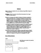
A filament lamp is a type of light bulb which has a coil of wire inside known as the filament. When current passes through, the wire heats up and thus produces light. This does not relate to Ohm’s law, because the temperature does not remain constant. This is because the resistance increases as more current passes through due to more amounts of electrons trying to get through in the same amount of space. As the resistance increases, energy is drawn from the current which is not allowed through and therefore the filament heats up even more which results in the temperature increasing. Therefore, the graph for a filament lamp would be as follows:
The current is no
longer proportional to
Current, I the voltage.
Voltage, V
The aim of my coursework is to investigate how the resistance of a nichrome wire varies in accordance to the length of the wire. Using a meter ruler to measure the length of the nichrome wire, I will continue to increase it in 10cm intervals whilst performing each test thrice to achieve reliable and constant results. The amount of current let through will not vary in any of the tests.
However, before conducting the actual investigation I carried out a preliminary investigation in which my aim is to find out how current varies with voltage when using a fixed value resistor and when using a filament lamp. I conducted this test only once for each number on the power pack.
Prediction: I predict that as the length of the nichrome wire will increase, the resistance will also increase. This is because as the length increases, the atoms will also increase in the wire, thus restricting the path of electrons which will not be able to move about freely.
Apparatus
- AC Power Pack
- Voltmeter
- Ammeter
- Switch
- 1 meter of Nichrome wire
-
6 Wires (4 crocodile clipped)
Method
- Set up series circuit as shown above.
- Switch AC Power on and keep dial at 5.
- Ensuring that all wires on the nichrome wire are at correct number on the meter ruler, press the switch.
- Keep it pressed for a few seconds and record the steadiest readings of both voltmeter and ammeter.
- Repeat twice more, and then move wires up to the next distance going up in 10cm.
- Repeat step 4 three times.
- Continue increasing the length at 10cm intervals, making sure that at each number the experiment is repeated three times. Stop at and including 100cm.
- Record all results.
Health and Safety
- Hands should be kept dry at all times to prevent electric shocks
- Work surfaces must be free from all equipment except for necessary tools
- Loose wires must be tucked to sides carefully
- Do not touch the nichrome while a current is passing through in case of getting burnt.
- Do not use frayed or bare wires.
- If gloves are used, they should not be plastic as this material can burn, instead use mittens.
Variables
To keep my test fair, I intend to keep some things the same and change the others. Factors which I will keep the same are:
- Amount of current being let out from power pack
- Number of wires
- Person who will read the voltmeter and ammeter, and who will press switch
- Intervals in which length will be increased i.e.10cm
Factor which will vary is:
Graph Analysis
The graph clearly shows that as the length increases, the resistance does likewise. At the beginning of the experiment, the length was 10cm and the resistance 1.05 ohms. Halfway through, with the length at 50cm the resistance became 5.31 ohms and at the end of the investigation the resistance had increased to 10.95. Therefore, the prediction which I made at the beginning saying that as the length would increase, so would the resistance has been proved to be correct. I think that the results which I have obtained are constant enough to prove my hypothesis correct.
The resistance has increased because although the current was kept the same, it had to travel a longer distance thus slowing it down. Due to the wire being narrow, the electrons could not move about freely and thus their restricted movement also caused slowness. A person trying to walk hurriedly down a crowded street is exactly the manner in which electrons behave when the length is increased.
From my graph it can be seen that I have attained four anomalies. Two of these seem to be only slightly incorrect and I would therefore put it down to human error. For example, attention could have been diverted during pressing the switch and reading the meters, or the wires may not have been connected properly etc. However, the readings which were taken at 60cm and 40cm seem to be very incorrect. This could have been because the current flowing may have fluctuated and thus caused reduction in the current which was flowing through the nichrome wire.
By looking at my results table it can be seen that the final three resistance calculations to do not fit in the pattern which the rest of them have taken. Again, I put this down to the unreliability of electricity and this increment would probably have taken place because the amount of electricity flowing increased.
Evaluation
The method for my investigation was very simple and straight-forward. My results were mostly relating to each other relatively well and this shows that my method was satisfactory. The experiment did not take long to conduct and was uncomplicated.
Although I felt the experiment was dependable and suitable due to the less amount of equipment needed, to improve the investigation, I could have kept the wire at the same temperature all throughout or kept the time I left the switch on same all the time. This would have helped make the results reliable with more consistency. In improving the safety of my investigation, I could have used a circuit breaker which would have automatically all power off if the current flowing became abnormal.
On the other hand, to extend my investigation I could have increased the amount of current flowing from the power pack as well as the length of the wire. I could have increased the length of the wire too, or added another component such as a bulb in tee circuit to see what effect this would have on the resistance.
My investigation was based on the length of the wire, but out of the other three remaining factors I could have investigated any of them with the length too to understand what effect they would have on resistance.
To increase the current at each step I would simply turn the dial of the power pack to a desired number which would thus give me an idea on how more current would affect longer length. Increasing of the length of the wire could have been done by using a 2m or 3m wire which would have showed what the same amount of current would do in such a long distance. The wire could also have been coiled up as this would show how fast current travels in different shapes.
By the other three factors I mean the material could have been a different type used, i.e. plainly copper instead of nickel and copper together, or the diameter of the wire could have been increased as to which I predict that the resistance would have decreased due to electrons being able to move more freely. I could also have changed the temperature by keeping a Bunsen burner burning near the wire to see the effect of temperature on resistance.
Overall, on a scale of 1 to 10 my investigation went at an eight. It could have been improved and extended by the above-mentioned factors.
Preliminary Investigation procedure and results
Aim
I will use both a filament lamp and a fixed value resistor in a series circuit to see how the current will vary with voltage using each apparatus.
Prediction
I predict that with the increasing of the current, the voltage will also increase. This is because voltage is the force which drives the current, and as the current will increase the force will also act likewise.
Apparatus
- AC Power Pack
- Ammeter
- Voltmeter
- Switch
- Fixed value resistor/ Filament lamp
- 6 wires (both crocodile clipped and slot-in types)
Method
-
Set up circuit as shown above using the filament lamp or resistor depending on which ever one you are using in the investigation.
- Keep the dial on the alternating current power pack at 1.
- Press switch and take readings of both voltmeter and ammeter.
- Turn the dial up in one’s always taking the readings at each number.
- Record all results and turn power pack off.
Results for investigation with fixed value resistor
Results for investigation with filament lamp
Graph Analysis & Evaluation
The first graph which has the results of the investigation with the fixed value resistor relates in perfect precision to Ohm’s law. The current is directly proportional to the voltage, meaning that my prediction was also correct. There are no anomalies and therefore I have accepted these results as reliable and constant.
The second graph however, does not relate to his law because the temperature was not kept constant. The bulb only glowed after it was heated up and this is obviously changing the temperature. In the background information which I have provided at the beginning, I have also included a graph which shows what would happen when the temperature is not constant. Here, my graph shows the same thing, meaning that although the voltage increases with the current, it is not proportional to it. My results again link to each other fairly well and have a steady consistency in them.
To achieve more accurate results I could have repeated the experiment more. In extending the experiment I could have added additional apparatus such as another resistor or another bulb etc. to understand their effect on resistance.
My investigation overall went smoothly due to a reliable and simple method.