This is because when the current of the light bulb increase twice. The power of the light bulb will increase four times. So the brightness of the light bulb will increase four times as well. The brightness of the light bulb and the resistance of the LDR are in proportional.
So the resistance of the LDR increase four times.
Fair test:
But there are some variables, which can also affect the brightness of the light bulb:
- As the reasons show above, the brightness of the light bulb plays the main role in affecting the resistance of the LDR.
- The distance between the light bulb and the LDR. When the distance between the light bulb and the LDR increase, the light is become less intense, so the resistance of the LDR is higher when it is further form the light bulb than when the light is closer.
- The brightness in the room. As the brightness surrounding the LDR will affect it s resistance, if it is brighter is the room, the resistance of the LDR will be lower.
In the experiment, I am just going to investigate how the current of the light bulb affect the resistance of the LDR. To make the experiment a fair test, I am going to keep the surrounding brightness and the distance between the light and the LDR the same. To keep the surrounding brightness the same, I am going to use a black tube, which makes the surroundings black, except for the light bulb. It also keeps the distance between the light and the LDR the same; I am going to put them in a fixed place.
In order to change the brightness of the light bulb, I am going to use a variable resistor. Increasing the resistance of the variable resistor will increase the resistance in the whole circuit, so the current will decrease in the circuit, just as the current decreases in the light bulb. This will cause the power of the light bulb to decrease and it will become dimmer. Otherwise, the light bulb will get brighter.
Constant factors, which keep the same the experiment a fair test:
The power supply must stay on 3V in both circuits;
The wire must be the same thickness;
The equipment should be kept the same;
the distance between the LDR and the light bulb must remain unchanged.
The Variable factor
Vary the current in the light bulb circuit by changing the resistance of the variable resistor.
Safety:
- As this experiment involves electricity, I will handle it carefully.
- I am going to only use a voltage of three volts so the wire will not burn.
- I will be careful when touching the wire, as it may be hot.
- Start on the lowest current, so the wire then will not melt or burn instantly.
- Put the variable resistor in the largest resistance so as to make sure that not too much current flows through the circuit.
- Be careful when the wire is connected, as it will get hot.
- Make sure that the current is going from the positive pole to the negative pole by connecting the right pole.
Apparatus:
Resistance is the force; it’s proportional to the voltage across the resistor and opposes the flow of an electric current around a circuit. The resistance is measured in Ohms. It is equal Voltage divided by current. The equation is as shown below:
Resistance=Voltage/ Current
In order to measure the resistance change in the LDR, I will need to measure the Voltage across the resistor and the current around it.
As the resistance of the LDR is so small, we need a fixed resistor to maintain the resistance in the circuit. If not, the current in a resistor will be too big and cause too much current flow through the LDR and it will be broken.
Changing the current of the light bulb can affect the power, therefore it will affect the brightness of the light bulb. In order to change the current, I will use a variable resistance to change the sum of the resistance in the circuit, because the current is equal voltage divided by resistance. As voltage in the circuit stays the same, resistance and current are in inverse proportion.
1* 20mA ammeter
1* 200Ma ammeter
1* digital voltmeter
4* 1.5V buttery: two for both circuits
1* 100 Ώ fixed resistor
1* 1-13.7 Ώ variable resistor
1* LDR
1* 60 m A, 6V light bulb
10* short wire
2* switches
Preliminary experiment:
I am going to carry out a preliminary experiment to see are there any other factors that could affect the experiment and also to see whether the apparatus I chose is suitable for the experiment. Can I improve my method?
I am going to connect the circuit as show below:
When I connect the circuit, as far as I switch on circuit 1, the reading range of the ammeter is too small-- 48.4-52.8MA. My teacher gets me a better circuit, which can give me a better result, which get me an ammeter reading range from 0.1MA(when the variable resistance is smallest) to 51.1 MA (when the variable resistance is biggest). This gives me a large range of reading which is good for my experiment.
After I change the circuit, I put the LDR upon the light bulb when it is the brightest and dimmest, and I find out the reading of the ammeter and voltmeter:
When the light bulb is brightest: I2=0.72 MA V=2.91V
When the light bulb is dimmest: I2=0.02 MA V=2.99V
The ammeter reading is from 0.02MA to 0.72 MA, which tell me the range is suitable for my experiment.
As the result, I am going to do the experiment use the circuit graph show below:
Apparatus for my real experiment:
6V direct power supply
2* 1.5V buttery
1* 100 Ώ fixed resistor
1* 0—13.7 Ώ variable resistor
1*light bulb: 60MA, 6V
1*20MA ammeter
1*200MA ammeter
1*digital votmeter
1*switch
Method
The circuit was set up as shown above. A table was drawn out and the results were recorded.
To improve the accuracy, compared to my preliminary results for my main
Experiment, I have decided to use a 20MA ammeter in the 1st circuit and use a 200MA ammeter in the 2nd circuit.
To collect the data for my graph I have chosen to take a range 2.5MA of the current of the light bulb. I have chosen a range of 20 as plot an accurate graph; I will need at about 20 points to mark on the graph if I want to make precise and reliable results, to see if there are any patterns and trends. I have also chosen to take two repeats at each length and then take an average, to get reliable results
EVIDENCE
R (LDR)=V2/I2
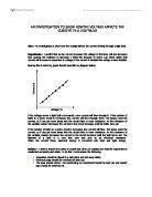
The graph shows that when the current of the light bulb is between 0-25 MA, the resistance of the LDR is very big-nearly 300Ω and not changed too much. After the current of light bulb gets bigger from 25ma, the resistance of the LDR decrease as the current of the light bulb increase. The change of the resistance of the LDR is bigger when the current is smaller.
In my prediction, I stated that:
If the light bulb becomes brighter, the resistance of the LDR decrease.
From my graph on the previous page, it shows that I am right. I can see that the resistance of the LDR is in strongly correlation to the current of the light bulb after 25MA. It also shows that the change of the resistance of the LDR is bigger when the current is smaller. However, the resistance of the LDR remain nearly the same when the current of the light bulb is smaller than 25MA. I know this because the Line of Best Fit is a curve line.
The current of the light bulb affects the resistance of the LDR because as the brightness of the light bulb, which depends on the power of the light bulb increase or decreases as the current of it increases or decreases. As power is equal current2 time’s resistance. As the current increase twice, the power increase four times. In addition, the resistance of the LDR depends on the power of the light bulb, so as the current increase or decrease twice; the resistance of the LDR also increase or decrease twice.
From the graph it is easy to tell that the theory is correct and therefore my results reliable. I think that my results are suitable to confirm my prediction and support a conclusion. I know this because Textbooks say that ‘when the light bulb is bright, the resistance of the LDR is low; otherwise, the resistance of the LDR is high.
The table also shows that when the current of the light bulb increase, the current of the LDR increases and it voltage decreases.
However, my prediction of the graph is wrong. I predict that the graph will be:
But the graph of my experiment is:
Why the resistance of the LDR is much bigger and doesn’t change until the current of the light bulb reach 27.5 MA?
This is because when the current of the light bulb is 17.5MA, the light bulb is not bright at all, so the surrounding environment of the light bulb is dark, and this causes the resistance of the LDR is very big. As the result, the current flows through it are very small (nearly 0). When the current of the light bulb increases form 27.5 MA to 60 MA, the resistance of the LDR decrease as well, so the current increase.
Evaluation
From my results table and graph, I can see that my results that I collected are quite reliable and accurate. I know this because my results table shows a few, individual anomalous results; the anomalous result when the current of the light bulb at 32.5 ma. All the other points are extremely close to the line indicating that my results are accurate.
In the Analysis and the graph I have shown two main anomalous points, this means that there must have been a slight error in my experiment. Although the graph is overall accurate and the results precise it is easy to see, the anomalous averages plotted because they do not all lie along the same best-fit line. The graph shows that my results are reliable as there are only one main anomalous points, (which are easily accounted for) to improve the reliability of my results, I could do more repeats in doing this my average would be more reliable.
I think one of the reasons why my experiment is quite accurate is because I tried to keep the distance between the bulb and the LDR the same; I also keep all the other confounding variable (such as the power of the circuit, the wire, the equipment and the distance between the LDR and the light bulb) the same. I also varied the current of the light bulb as accurately as possible.
The anomalous points may because I did not put the black tube in the right position, so some of the light in the room get into the LDR, this cause the resistance lower than it supports to be. Another reason for this is that the ammeters and the voltammeter flicked between a decimal point, I maybe could have thought it was the wrong number and therefore would have ended up with the wrong average resistance.
One of the difficulties in this experiment is to control the current of the light bulb, when I carried the variable resistor R1, the current of the light bulb changed rapidly, so it is hardly to control it exactly what I want.
During my experiment, I have noticed several mortifications I could make to improve on the Investigation if I was to repeat it.
The first of these modifications would be I could use a new or higher quality digital voltmeter and ammeter.
The graph shows that my results are reliable as there are only two anomalous points, to improve the reliability of my results, I could also have repeated the same lengths of wire more times.
As well as making these modifications, I could also expand on my investigation by measure the voltage of the light bulb in order to find out the power of the light bulb.
This is because the brightness of the light bulb is depended on the power of the light, in order to find out he power of the light bulb, I will need to know the voltage of the light bulb and then use power=current* voltage to find out eh power.
I will use the circuit and method used, as it was quite suitable although I would make the modifications above to improve my results. If I did this experiment again I would defiantly use top quality equipment, I would control the entire confounding variable, which includes the brightness of the room.
My alternative conclusion is that: the resistance of the LDR decreases as the current of the lamb decreases.