Equipment list
- 6V power supply
- Voltmeter/multimeter
- 10 Ω Rotary potentiometer
- 4 copper wires
- 3 crocodile clips
- 100g weight
- block of wood
- G clamp
180˚ protractor
Method
The rotary potentiometer I plan to use is a small 10Ωresistor because I believe it would provide the most accurate results with a small power supply. It is also small so it would be able to be easily fixed into a position if need be.
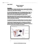
To be able to calculate the amount of lean of an object you first need to know what the resistance of certain angles are in relevance to resistance this is known as calibrating. To do this set up the rotary potentiometer with an arm attached to it. Then set up the wires connected to a 6V power supply as shown in the diagram bellow (I chose to use a 6V power supply because I believe that a lower power would not results with a large enough difference to measure and a higher one may be to powerful to the potentiometer). You then need to attach the rotary potentiometer to an 180˚protracter. Make sure the arm on the potentiometer is halfway along then line it up with the 90˚line on the protractor making sure the center point of the rotary potentiometer is and the center point of the protractor. Secure the base of the rotary potentiometer in place with blue-tact then move the arm round so it is inline with 0˚. Turn on the circuit and take the voltage measurement across the rotary potentiometer. Do every ten degrees, and then repeat to check that results are similar. If results aren’t similar make sure that the base of the rotary potentiometer is secure to the protractor.
Results
After my first and second set if results I was able to see there was a slight correlation between angle and voltage. However I then realized that my sensor had slipped slightly making my results in accurate. I then re-adjusted my equipment and took down the results again. This time it was clear to see a positive and similar measure of results. Its is clear to see that from my results I managed to achieve constant readings between to angle of 40 and 160 with a difference of 20 volts of each change of 10 degrees making it a very measure reading. Between 0 and 20 I was un-able to achieve a reading this is most likely because the high resistance wire within the device was no longer in contact with the sliding contact. As a result the circuit was incomplete so I got no reading.
From looking at the graph I have drawn it is easy to see a correlation between voltage and degrees. Between 1.4 and 3.9 volts I have come up with a formula of (2.8 – the voltage reading) x 50 to give you the angle of degrees from vertical. Therefore you are now able to tell at what angle you have pivoted the device by looking at the voltage reading then reading the angle off the graph or by calculating it using the formula.
After calibrating the device you need to attach it to the object you with to measure the extent of it lean. I chose to attach it to a chair legs just as an example of how it would work. To do this you need to mount the rotary potentiometer to a block of wood I used a glue gun to do this. After attaching it set up the circuit in the same way as you did for calibrating the device. Then attach the block of wood with the device still attached to the object you wish to measure using a G-clamp to do this. You need to make sure the device is perpendicular to the floor so that the arm of the potentiometer will swing down naturally when a weight is attached. You will now need to turn on the circuit and place a weight on the end of the arm so it swings down. Then pivot the device so that you get the same reading from the voltmeter as you did from when the device was at 90˚. You need to do this because otherwise the results you obtain would not be calibrated the same way as the earlier measurements.
One problem with this setup however is that the device will only measure the angle of lean parallel to the direction of the device.
After attaching the device to the chair I tilted it over until the chair started to fall over. I then held it and took the volt reading at the point at which the chair was balanced. The reading I got from the voltmeter the first time was 3.52 volts. I then put the chair back to standing position and re-tried the experiment. The reading I got this time was 3.58 volts, which is very close to the one before. I took an average of these to results which was 3.55volts and using my formula I worked out the angle.
(2.8 - 3.55) x 50 = -37.5 from vertical, which also works out as 52.5˚ from horizontal.
I then asked a friend to find the point at which they believe the chair would topple over. I then measure the angle at which the chair was leaning with a protractor from the pivot point. This angle work out to be 54˚. I believe this is a good representation that my results are accurate because it is a lot more difficult to work out the angle of a chair leg because a protractor does not sit perfectly on the floor so it was not lined up with the pivot point exactly so there was a margin for error.
However my results are not a true reflection of then angle at which the chair will fall over. Due to the device being attached to the chair it would have slightly changed the weight distribution and as a result the chair would topple at a slightly different angle. Though due to only a small weight being used I believe the result wont be much different.
Other possible uses for my device you be to place the device up against the corner of a door/window. So that you will be able to calculate at what angle it is open.
It may also be possible to use a rotary potentiometer to measure the amount of G-force endured by cars and other transport. By place a rotary potentiometer with a free-swinging weight attached to it in a car. The forces due to acceleration and braking will cause the device to swing either forward or back. You could then use the information gathered by the voltmeter to work out the number of G’s, however this would be hard to calibrate in the first place.
Evaluation
I believe my experiment went quite well; I got what I believe to be realistic and accurate results, which appear to match what they are measuring. If I was to extend my experiment I may have been able to use my device to work out points such as the center of gravity of certain objects. I would also try out my ideas with different rotary potentiometers and power sources to make sure that my results match. Another extension on this experiment would be to have made another similar device which I would have been able to attach at a perpendicular angle to the one I made so I would be able to calculate the lean in the other adjacent direction.
One major thing I would like to have improved with my experiment and result was the amount of possible human error. Though I a class room this is hard to avoid I believe I could have taken a lot more measurements to check my results. Though all together I believe the experiment went well and my results are good reflections of that.
In conclusion, I have managed to construct a calibration graph that would enable me to work out the angle at which an object is leaning by knowing the voltage. An example of a device like this being used in commercial industry or construction could be at the top of cranes or tall buildings. Current uses of devices similar to this are likely to be found at the top of tall skyscrapers to measure the amount of sway due to wind. In modern skyscrapers they are now linked up computer that in turn is linked up with counterbalancing weights that try to prevent excess lean. If the builds where to lean to much then they would be likely to put the structure under to much stress and as a result they may fall over.