In the above circuit the rotary potentiometer could be used to give various readings at different angles, by the changing length of the track.
As the blue arrow moves downward in relation to the page, the resistance of the red section, which is having the voltage across it measured increases. As a result it draws more voltage than the green half. The further the arrow moves down, i.e. the more the window opens, the greater the resistance of the red half of the potentiometer, thus the greater the voltage it draws. These voltages can then be recorded at a series of predetermined angles, and thus , once calibrated can be used to give any angle at which the window might be open.
The other possible circuit 2, was as in the diagram below. Again the rotary potentiometer could be substituted directly for the slider.
In this circuit, only 1 portion of the track within the potentiometer is connected. In this case it is the brown section of the track (refer to diagram). The voltage from the battery is split between the fixed resistance, R1 and the potentiometer, R2, according to the relationship:
V1 R1
=
V2 R2
When the window is closed, the track
length is 0. Therefore the resistance of the potentiometer is 0, and all of the voltage is going to the fixed resistance,
producing a voltage reading of 0 across the potentiometer when the window is shut. In reality not quite all of the voltage will be reaching the fixed resistor, because the power supply will have an internal resistance which will draw some of the voltage. As the window is opened, the arm on the rotary potentiometer rotates, causing the track to get longer, thus increasing it ‘s resistance. Thus as it moves down , it draws more voltage as its resistance increases. These voltages can then be recorded at set numbers of degrees and thus the potentiomete5rs voltage can be used to determine the number of degrees at which the window is open.
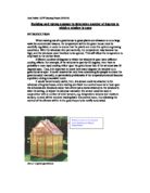
The potentiometer could be attached to a greenhouse window for use as a sensor in the following way:
After having evaluated the practicalities of the two methods, I have decided that the must suitable would be the rotary potentiometer. This is because it can be attached more easily, and because it is a rotary device, it lends itself to angular measurement for more readily.
The slider would firstly have to have a hinged arm attached to it before it could be used to measure the angle. This is to the fact that to change its resistance it needs to be pulled in a straight line. Furthermore, the majority of sliding variable resistors are too small. They would not be long enough to cope with a window opening to 180 degrees. Consequently, I will be using a rotary potentiometer. How I will do this will be discussed in the following section, “FINAL METHOD” .
FINAL METHOD
In order to determine the number of degrees at which a window is open I will be using a rotary potentiometer. I will connect my rotary potentiometer into two different circuits, both of which give me different voltage readings at different angle of turn of the rotary potentiometer. I am using 2 different circuits in order to see which circuit provides me with the greatest linearity and sensitivity. The circuit diagrams below show the two circuits that I will use:
Circuit 1 Circuit 2
In order to determine how many degrees the arm on the potentiometer has turned, I attach a thin piece of balsa wood. I will then place the potentiometer onto a piece of paper with markings in it signifying every 10 degrees. This will allow me to line the balsa wood up with the markings, so I can record the voltage every 10 degrees. The diagram below illustrates how this will work:
I will be recording the voltage for every 10 degrees of turn, as this will be enough to produce a suitable calibration graph. Once I have produced a graph, the voltage can be used to determine any number of degrees of turn. Taking reading for every 10 degrees ensures results are close enough together to create an accurate graph.
I will take reading for my results from 0 degrees to 180 degrees. This will give me all the results necessary, because it incorporates all the possible values to which the window can be open. Assuming the window is shut when the potentiometer has been turned 0 degrees, then when the turn is 180 degrees the window is at a maximum, in terms of how much it can open.
I will also use 2 different voltage supplies in order to see which provides the most linear sensor, and which supplies the most sensitive sensor. I will be using two different power supplies. These will be 3 volts and 6 volts. Both of these voltages can be supplied by a fairly discrete power supply, and I can make predictions about the characteristics for other voltages from the patterns that emerge, thus making it unnecessary to take results with a greater number of supplies. I have also chosen 6 volts as my maximum supply. I also did not deem it sensible to go below three volts. This is because the potentiometer, which gives a linear output, must read approximately 3 volts when at maximum resistance, if the battery is supplying 3 volts. Thus, if the total number of degrees in one turn is 300. Thus for 10 degrees of turn , the increase in voltage must be equal to 3/10 = 0.1. Any less than this and it would become hard to distinguish between the voltage reading, especially when error is
taken into account. It follows then, that 6 volts will give me 0.2 volts per 10degrees,
which again is a round number. This makes it easier to read the scale. A supply such as 5 volts would give me 0.16 reoccurring. This is an awkward number to read of a screen and thus a supply of 5 volts would not be a sensible choice. I will also be using a fixed resistance in circuit 2. This is required not to be too small, as If it were, then after only a few degrees of rotation, the rotary variable resistor would draw all of the voltage. If on the other hand it were too big, then the increase in voltage for every 10 degrees would be much too small, and difficult to detect. When at maximum resistance, the rotary potentiometers resistance is 5000 ohms, therefore a suitable fixed resistor would have a value of about 1000 to 2000 ohms. I will be using a fixed resistor of 1200 ohms.
The results of my experiment are shown below, in the results section of my project.
RESULTS
CIRCUIT 1: The following results are my results for circuit 1. For a diagram of circuit 1, refer back to page 5.
I will now present my results on a calibration graph, showing the number of degrees that the rotary potentiometer has turned against the number of volts across it. This will allow me to observe the linearity and sensitivity of the sensor with the two different voltage supplies. This graph can be observed on the next page.
ANALYSIS
The graphs show that my sensor is fairly linear, for both of the voltages. This is indicated by the fairly straight nature of the graphs, for both voltages. Although neither graph is completely straight , It is probably not the sensor itself that was at fault but numerous errors that occurred during the taking of the results. These include both precision and procedural errors.
From the graphs it can be seen that the line representing the sensor with the six-volt supply is more sensitive. By doing some gradient calculations this can be proven, as gradient is equal to:- Y/ X . This is the equivalent of voltage across potentiometer / number of degrees. In other words, the gradient is volts.degree-1 .
-
The gradient at 30 degrees for the sensor with the 6 volt supply,M1, is:
M1 = 0.74 / 30 = 0.02 volts.degree-1 (to 1 S.F. )
-
The gradient at 30 degrees for the sensor using the 3 volt supply, M2, is:
M2 = 0.31 / 30 = 0.01 volts.degree-1 (to 1 S.F. )
The above calculations clearly show that the line representing the graph for 6 volts is much steeper, and thus the sensor was more sensitive. It is fairly logical that the sensor using the 6-volt supply should be the more sensitive. This is because the potentiometer can still only turn by 300 degrees, however there is a greater increase in voltage. Therefore the total number of volts per degree = 6/300 = 0.02, whereas if the total supply is 3 volts, then the number of volts per degree = 3/300 = 0.01.
The sensor was quite adequate for its purpose. It gave a fairly linear output, therefore any voltage can be used to determine how many degrees the window is open. The sensor using a six-volt supply was slightly superior because it was more sensitive.
CIRCUIT 2: The following results are for circuit 2. For a diagram of circuit 2, refer back to page 5.
Again I will present these results on a graph, in order to get a better idea of their linearity and sensitivity. This calibration graph can be seen on the next page.
The graph on the pervious page shows that this version of my sensor is not very linear. The gradient of the graph reduces as the number of degrees becomes larger. This reduction in gradient represents a reduction in sensitivity, as gradient is effectively: voltage across potentiometer / number of degrees. In other words, the gradient is volts.degree-1 . I will do some simple gradient calculations to show there is a reduction in sensitivity as the number of degrees is increased.
- The gradient for the sensor using the 6 volt supply at 30 degrees was:
M = 1.6/30 = 0.053 volts.degree-1 (to 2 S.F.)
- The gradient for the sensor using the 6 volt supply at 150 degrees was:
M = 0.3/20 = 0.015 volts.degree-1 (to 2 S.F.)
These gradient estimates display a clear reduction in gradient for the sensor when used with a 6-volt supply.
- The gradient for the sensor using the 3 volt supply at 30 degrees was:
M = 0.69/30 = 0.023 volts.degree-1 (to 2 S.F.)
- The gradient for the sensor using the 3 volt supply at 150 degrees was:
M = 0.2/20 = 0.010 volts.degree-1 (to 2 S.F.)
Again, these gradient estimates display a reduction in gradient for the sensor using the 3-volt supply.
The reason for this version of the sensor not being very linear is that for small resistances, the overall resistance is lower, thus the increase in resistance caused by a rotation of the potentiometer accounts for a larger proportion of the resistance, thus drawing a greater amount of voltage, had the overall resistance of the circuit been larger. This is easier to explain using the formula:
If the rotary potentiometer, r1, is turned from 0 to 10 degrees, then the overall resistance of r1 increases by approximately 17 ohms. This means that the total resistance of the circuit becomes the resistance of the fixed resistor, plus the 17 ohms.
This calculation clearly shows that the voltage supplied to the rotary potentiometer will increase by
If we now consider that the rotary potentiometer is turned from 180 degrees to 190 degrees, it can be seen that the increase in voltage is not as great, because the total resistance of the circuit has still increased by 17 ohms, however it was greater to begin with.
This clearly shows why there was a reduction in sensitivity, displayed by the calibration graph.
I it is also possible that the reduction in sensitivity was also caused by the fixed resistor. However, this factor is not as significant as the one previously. The sensitivity also drops with time. The longer the circuit has had a current flowing through it, the lower the sensitivity seems to be the general trend. This reduction in sensitivity may have been contributed to by the heating effect on the fixed resistor. As the fixed resistor is a metal, the hotter it gets the greater its resistance. This is because no more electrons become free to move. Already moving electrons scatter from the vibrating lattice and so move a little less freely as the temperature rises and lattice vibrations increase. Consequently the amount of voltage that the fixed resistor draws increases, and thus there is less voltage available for the potentiometer, and there is a subsequent decrease in sensitivity.
The gradient estimations show that the sensor used with the 6-volt supply is more sensitive, i.e. the gradient is greater. These follows, because with a six-volt supply, there is more voltage for the same number of degrees, therefore the increase in voltage per degree must be greater.
From my results, I can conclude that the sensor is superior when placed in circuit 1. This is for the simple reasons that it is for more linear. If the linearity of the sensor changes, depending on how long the sensor has been turned on, then it is
useless as a sensor, because the voltage readings cannot be used to determine the number of degrees to which the window is open.
My optimum sensor includes the rotary potentiometer connected to a six-volt supply (circuit 1). This gives me an optimum sensitivity and linearity.
EVALUATION
There are a number of possible errors that could have occurred, making my sensor inaccurate and my results unreliable.
Percentage error is something to be considered. Each reading was taken to the nearest degree. Therefore, it could be 0.5 of a degree out. In terms of my optimum sensor (circuit 1, 6 volts), assuming it was completely linear accounts for a fairly significant voltage reading error. The gradient was approximately 0.02 volts.degree-1. Thus if the maximum error was incurred, then my reading could have been + or - 0.01 volts out. This prevents me from being able to take a voltage and convert it to the nearest degree. I believe that I could only justify converting voltage readings to the nearest 10 degrees. To reduce this error, more accurate markings could have been used, e.g. markings for every half a degree. This would make the error +/- 0.005. So for a result of say, 10 volts, the percentage error would be (0.005/10)*100 = 0.05%. Whereas previously, with the less accurate equipment, the percentage error for a reading of 10 volts was (0.5/10)*100 = 5%. This is a significant reduction in error
Furthermore, in terms of systematic error the equipment may have been at fault. For example, the results could have been 0.2 volts out for each reading. Thus they are calibrated wrongly .If the rotary potentiometer was then placed into a circuit using an alternative voltmeter, the voltmeter readings could not be used to determine how many degrees the window is open. The obvious way to eliminate this error is to test the voltmeter before its use.
There are also random errors, which may have occurred, making my results inaccurate. These errors are unquantifiable, however their effect and significance can be discussed. Firstly, the temperature on the day of my experiment5 may have fluctuated. An increase in temperature could have effected the resistance of the various components within the circuit and thus make my results inaccurate.
Bad contacts may have also effected the experiment on the day. Checking contacts could easily eliminate this error.
Although I do not believe that any errors occurred, I have been unable to identify any anomalies. This is because I took only one set of results for each circuit at each voltage. To improve my experiment in the future, I could take two sets of data. This would allow me to eliminate anomalous results, by repeating experiments for which the two results did not match.
In terms of its fitness for purpose, angles to the nearest 10 degrees are perfectly adequate. It is unlikely that the difference in cooling effect upon the green house between the window being open 1 or 2 degrees is noticeable. However, the difference in cooling effect between 20 and 30 degrees on the other hand , may be large enough to have a profound effect. My sensor is equipped to detect the openness of the window to within 10 degrees. Thus , in this respect at least my sensor is adequate.
The sensitivity of my sensor could be greatly improved. If I were to increase the voltage coming from the battery pack, I could greatly increase sensitivity.
My results for circuit 2 showed very non-linear characteristics. Although I cannot be certain as to the reasons for this, I believe it is probably due the heating effect on the fixed resistor within the circuit, as I explained in the previous section. In this case, I estimated a suitable value for the fixed resistance. However in hindsight, I perhaps should have calculated what resistance I required to give me a specific increase in voltage for every 10 degrees. For example, I could in fact have chosen to obtain increase in voltage of 0.2 volts when the total supply was 6 volts for circuit 2. I would then use the equation:
R1/ (R1 + 5000) = 3/6.
In the equation above R1 is the value of my fixed resistor. 5000 is the value of the resistance of the potentiometer when it is turned to its maximum resistance. The 3 is the voltage I would like the potentiometer to draw when at maximum resistance. This is because this gives me 0.1 volts for every 10 degrees of turn, as the total number of degrees that the potentiometer can turn is 300. The 6 indicates the total voltage supply.
R1 = 0.5(R1 + 5000)
R1 = 0.5R1 + 2500
0.5R1 = 2500 .: R1 = 2500/0.5 = 5000ohms.
This would have been a better value to use as my resistance, and would be an improvement I would consider if doing the experiment again.
Overall, my circuit 1 sensor was fit for its purpose when used with a six-volt power supply. It was quite linear and had a suitable resolution for its purpose, of approximately 10 degrees.