Electronic Combination Lock - create a secure lock to protect a property from intruders.
Electronics Coursework Electronic Combination Lock
Aim:
* The aim of this project is too create a secure lock to protect a property from intruders. To do this I have researched how to construct an electronic combination lock. During this project I will create a lock that is a great deal more secure than a standard mechanical lock, the reasoning behind this is that an experienced locksmith can open a mechanical lock without any trouble. On the other hand an electronic lock will seem a lot more of an obstacle to open as you have to input 4 switches in the correct order to open the lock successfully increasing the security highly.
Research:
* I have researched some factory made electronic locks to compare with the design that I will make. Of course my project will be much simpler than some of the combination locks that I have found on the Internet. (http://www.quasarelectronics.com/3029.htm).
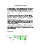
* One of the factors of the circuits that I need to consider is what the input would be (for example a keypad or simply switches.) I have decided that a keypad as an input is too complicated to build effectively and fault finding will be very difficult, because of this I will include 4 switches as the input to make the circuit simpler and easier to build, and fault find if there are any problems after construction.
* The second factor that I will consider is the amount of active components that are involved in the circuit, as one of the things that need to be included is three active components. I have found circuits that use too many active components; this would make building it very complicated. This is why I have chosen to construct the circuit below which includes 5 active components to minimise the complication of building the circuit.
Aim:
* The aim of this project is too create a secure lock to protect a property from intruders. To do this I have researched how to construct an electronic combination lock. During this project I will create a lock that is a great deal more secure than a standard mechanical lock, the reasoning behind this is that an experienced locksmith can open a mechanical lock without any trouble. On the other hand an electronic lock will seem a lot more of an obstacle to open as you have to input 4 switches in the correct order to open the lock successfully increasing the security highly.
Research:
* I have researched some factory made electronic locks to compare with the design that I will make. Of course my project will be much simpler than some of the combination locks that I have found on the Internet. (http://www.quasarelectronics.com/3029.htm).
* One of the factors of the circuits that I need to consider is what the input would be (for example a keypad or simply switches.) I have decided that a keypad as an input is too complicated to build effectively and fault finding will be very difficult, because of this I will include 4 switches as the input to make the circuit simpler and easier to build, and fault find if there are any problems after construction.
* The second factor that I will consider is the amount of active components that are involved in the circuit, as one of the things that need to be included is three active components. I have found circuits that use too many active components; this would make building it very complicated. This is why I have chosen to construct the circuit below which includes 5 active components to minimise the complication of building the circuit.