This device may be good but it is not as accurate as I would want, doesn’t work quickly enough, is too large and is not even an electronic gadget, which totally opposes the entire point of this project and would not even open the window.
Alternative design thermo coupling
A thermocouple could be used but due to its needs to be partially covered by a material like wood, which may be painted, or lined with, insulated materials like wool. However for production wood is not a very adaptable material. But having a plastic, which can be injection moulded or vacuum formed is very adaptable and economical.
A thermocouple is a temperature transducer consisting of two wires of different metals joined at both sides. If the two junctions of the metals at the ends are at two different temperatures an electrical current will flow around the circuit. This phenomenon is called the seebeck effect of otherwise known as the thermoelectric effect.
Useful materials
Useful materials needed have to be basically resistant to the elements like rain, damp, water, cold heat and other such conditions. Types of coverings could be aluminium alloys, plastics, and other coated metals. This however would not be suitable because my device has to be small and light, which is very hard to find metals in while plastics can be vacuum, formed or injection moulded into small shapes.
Useful circuits to process the temperature change
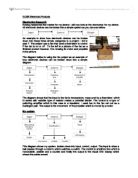
Potential divider
This is a standard circuit that consists of a heat sensor called a thermistor and variable resistor etc. This allows a certain amount of voltage that is being fed to the circuit depending on the light, temperature and the voltage. This could be very useful as it could act as a kind of protection for my components especially if I am to connect the circuit to the car battery, which runs on a higher voltage of 12 volts.
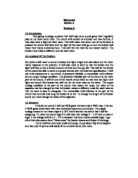
Amplifier
This could be used as a way to regulate the voltage so as to prevent surges or absences of voltage. It works by amplifying the voltage if it is too low and lowers it resisting the voltage if it is too high thus protecting the following component.
Logic gate
This will decide whether or not to set the components that could open or close the car windows in motion depending on the voltage signal it gets. There are many different types of logic gates, which could be compatible with my circuit, but on the one that I will chose is still undecided.
This list of products can be considered useful for detecting temperature changes
Thermistors are the obvious and most popular choice as they are a form of resistor that lowers its resistance as the temp rises, thus triggering my circuit allowing my device to work.
Thermoelectric temp sensor
I can also use a basic thermoelectric temperature sensor or thermo couple. This is just a type of transducer consisting of two wires of different metals joined at both ends. And if the temps of the two metals were different a current would flow around both pieces of metal. This would happen by one end being insulated and kept at low temp, but the other would be exposed and if the temp rises it would trigger the circuit and an electrical current would flow round.
Other useful circuits
Micro switch
This would send a signal to a logic circuit on whether or not to set on motion the process of cooling the car down, the signal given out could be interpreted as a one or a zero.
Timer monostable
The timer in my circuit would decide on how long the windows would stay open for sending a pulse of electricity (positive) so that for the length of time the pulses are going the sun window will be down. A timer monostable is made up of Ics (including 555)
Driving stage
At this stage the motor is set to open the sunroof and this is what actually opens the sunroof by driving the gears and other components.
Overall for my research I have also printed off computer circuit simulations of many tried out crocodile clips that I have made and though of and also some pcb wizard circuits including my final design and other variations.
Methods of construction
Methods of construction that I could use for the casing of my circuit are;
Vacuum forming
When a sheet of plastic is placed in a machine with a moulded or carved object below to which you want the resulting plastic to be a copy of. The plastic is then heated and moulded over the object. This method would be my choice method as it is quick and I have the equipment that I need.
Injection moulding
When a mould is used to gain a shape by having molten plastic injected into the mould. This is a good way as it is very accurate and good for small shapes and this is what I want the case for my heat sensor to be as a mass product injection moulding is much cheaper and cost effective, but for a one off that I am doing it is more expensive than vacuum forming for if a car manufacture was to incorporate them into their vehicles they would probably use injection moulding.
Specification
Has to be small and able to fit in a modern car as they have less room.
Has to have replaceable parts.
Intergratable with the car system e.g. (battery)
Must be cheap to make.
Flat so is inconspicuous.
Driving stage has to be able to open and close the sunroof.
A pet mode so the device is not in constant use.
Adjustable temperature gauge for the temperatures that is deemed acceptable to be raised or lowered depending on the user.
Has to be able to withstand the elements such as water heat etc.
Must have room for its own power supply.
Must have lead that can reach dashboard while circuit is in the roof of the back of the car to make it more adaptable to modern life.
Design proposals
Final solution
I have selected the best design for development and have decided to use the split circuit, which consists of two circuits interlinked by wires. I have chosen this because unlike the other designs it uses a smaller circuit board reduces space, as one of my specifications was to have a board that can fit into a modern car, which are rather compact. I have also decided to use this board because unlike the others it can drive the motor both ways forwards and backwards opening and closing the window, which is another specification.
Planning the manufacture
I was going to make a case out of wood as it is strong and due to it being an insulator it means there is a less chance of short-circuiting. But while making the case during a practical I decide to in stead make it then vacuum form over it so I could have a kind of mould to make other cases this made it cheaper to produce more and also because I found out that the wood I was using was very vulnerable to water and would waken and rot easily. I have chosen plastic for the manufacture casing, as over all in industrial practice it is very cheap as most things now a day are made of plastic.
Evaluation and testing
For my testing I hooked up every circuit board that I printed out and made up to a power supply and randomly checked if the solder tracks were all interconnected and if when turned on the properly the circuit actually powered the motor on, but not just one way but another depending on the currents charge. The performance of this circuit is in strict correlation with my specification this is shown below.
Has to be small and able to fit in a modern car as they have less room.
This was achieved by having a very small case and a fold over circuit, which made itself compact as it was in two parts. I was originally going to make one small circuit to fit in with this spec but since the ones I produced were too large due to the sheer amount of components needed I decided to go for the split design.
Has to have replaceable parts.
I achieved this by using for the circuit entierly common and cheap parts meaning it would be easy to find any needed new parts and cheap to buy them making this cost affective which was another spec.
Intergratable with the car system e.g. (battery)
I made this so by having put in extra resistors to cope with the 12v power supply from the car battery. I also made this spec by placing small holes in the sides of the casing allowing the wires to come out so they can be fixed in with the car system.
Must be cheap to make.
Using vacuum forming for the one off of making one case did this but on large scale manufacturing process I would use injection moulding as it is accurate and all would be identical. Vacuum forming was achieved by creating a model wood that was placed in the vacuum former meaning I have a permanent mould that will let me make more.
Flat so is inconspicuous.
Done in the vacuum former and by sanding down a block of wood into the exact shape and size that I wanted it to be in then moulding plastic over it.
Driving stage has to be able to open and close the sunroof.
This was made possible by using two separate relay coils so instead of just driving the motor one way it can drive it forwards and backwards depending on the charge of the current so it can drive it to open and close it.
A pet mode so the device is not in constant use.
A switch on the side, which will simply open or close the circuit allowing current to or not to flow (simply turning it off.)
Adjustable temperature gauge for the temperatures that is deemed acceptable to be raised or lowered depending on the user.
By having a variable resistor put in that was connected to a screw like cap poking through the top of the casing so the temp max could be turned up or down depending on the user.
Has to be able to withstand the elements such as water heat etc.
Simply by making the casing of a plastic instead of using wood, which i wanted to do from the beginning. This made it resistant to water instead of rotting like the wood would.
Must have room for its own power supply.
By having an intergratable 9v battery supply built in at the begining of the circuit seen on the PCB diagram. I wanted to use an extremely tiny battery but this was rather expensive so I decided to stick with the regular rectangle shape 9-volt battery.
Must have lead that can reach dashboard while circuit is in the roof of the back of the car to make it more adaptable to modern life.
Done by simply having extension leads able to be added on to the end of the circuit and by drilling holes in the case to allow connection to car battery supply.
In this project I could have further developed my circuit by maybe adding a remote sensor to turn it on or off this would make it more attractive to any wannabe buyers. I could have also done more testing on my circuits to be double sure that everything was fine as I had to back track twice when my testing was inaccurate to rebuild and in some case redesign the entire project. For my casing I could have used a harder plastic than the thinner one I sued as I found out that it was only a few mm thick and was easier to damage than I wanted it to be. Over all I think this project went quite well as the circuit actually works with every thing even the pet mode working. I also think it went well as every one of my specifications was met to an extreme high standard and next time if I was to do this again I would add more to my specification to make a more accurate project so that anyone could make it like adding the max and minimum dimensions of the case or even the components that must be incorporated.