Water level sensor
As Sensor Physics Coursework Water level sensor -By Leo Contents: Aim; Planning; Circuit Equipments needed; Theory Safety; Experiment; Problem & Improvement Tables & Graphs Evaluation Aim In ordinary life, water level sensors are quite widely used. For example: An oil level sensor inside an oil tank, to measure how much oil is left in it because we cannot see it every time, and just find the level on our meters. Also a boiler works on the similar principle, the water in the boiler is quite hot and if we want to see how much the water is, we will be hurt by the vapour. We need the meter for it too. Because water level sensors are very important and there is no alternative for it, I prefer to investigate water level sensors as my coursework. Planning My main equipment is the fixed resistor and uses a float to connect with it using potential divider. While the water level changes, the resistance changes as can be shown on the change of the voltage because the ohm's law: V=IR. For my circuit, when the resistance changes by the level of water, the voltage changes with direct proportional to resistance. As the water level increased, the Resistance of water level sensor Increase as well. So the voltage share will be change. using R=R1+R2 What is potential divider? The potential divider circuit is the voltage split up between the

Test and evaluate a linear position sensor, and identify a possible use for this sensor in every day life.
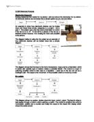
Outline For my experiment, I chose to test and evaluate a linear position sensor, and identify a possible use for this sensor in every day life. The experiment was done using a variety of apparatus, as seen in the list below, and was set up as shown in the diagram which follows. Apparatus: Retort stand with two clamps 100g, 20g, and 10g weights with holder Piece of string Sensor Precautions and Safety Safety was not a big issue when doing this experiment, as no harmful materials or apparatus were used. However, some precautions were taken. I made sure that I had enough space to carry out my experiment effectively, without worrying about knocking anything over; and when applying the weights to the sensor's mechanical contact, I made sure to this gently, and not drop the weights on, which could damage the sensor. Procedure After gathering and setting up my apparatus, the circuit was connected using a pair of connecting wires, a few crocodile clips, a power source, multimeter, and of course the position sensor. In this sensor, the exact circuit set up is not known, however there are two possibilities, both of which are shown in the two diagrams which follow. Throughout the experiment, a constant supply voltage of 5 V was used, so as to maximize accuracy of the readings. The multimeter, set in voltmeter mode, was connected across or in parallel with the variable

Building a mass balance to measure small weights (0g-100g) using a rotary potentiometer
BUIDING A MASS BALANCE TO MEASURE SMALL WEIGHTS(0g-100g) USING A ROTARY POTENTIOMETER Introduction: Nowadays, we have mass balances, weighing scales etc to measure masses but we hardly have devices that measure small masses. Sometimes, we may have to measure objects with small masses say 10g to 100g and my model is created backed up with this idea. Components Used: Digital multi-meter, Meter rule, Retort Stand, Clamp, Rotary potentiometer, Power supply (5V), Spring, Masses (in unit of 10g), 2k and 3k resistors, 1k variable resistor, amplifier. Reason For Choice Of Components: * Rotary Potentiometer: I used a rotary potentiometer so that when masses are placed on the meter rule the change in voltage (output) could be noted. The rotary potentiometer is of 5k Ohms but I connected it to a 5V power supply as a more convenient way of measure. As the potentiometer moves the resistance changes and also does the voltage. * 2k, 3k Fixed Resistor and 1k Variable Resistor: I used these resistors in order to make a Wheatstone Bridge so that there will be a significant change in output when masses are added to the meter rule. * Amplifier: I am using the amplifier in order to make my model more sensitive and obtain a more accurate result. * Spring: Without the spring, when masses a put on the meter rule, the masses will pull the rule till the masses came to rest on a flat

Palm OS Management
Palm OS Palm OS - Table of Contents Topic Page I. Introduction...........................................................................2 II. Aim of Palm OS.......................................................................3 * Flexibility...........................................................................3 * Ease of Uses........................................................................3 * Mobility.............................................................................4 III. Power Management..................................................................4 IV. Data and File Management.........................................................5 V. Memory.................................................................................5 * Overview...........................................................................5 * Architecture.......................................................................6 * Format..............................................................................7 * Allocation..........................................................................7 VI. Process Management................................................................8 VII.
Single Slit and Double Slit Diffraction
Single Slit and Double Slit Diffraction Objective To observe the diffraction patterns created by laser light passing through a single slit and double slit and to verify the equation which predicts the diffraction patterns in theory. Mathematical Theory n ? = d sin(?) n ? = d Procedure . Align a laser, a diffraction disk, and a light sensor mounted on a rotary motion sensor. 2. Allow the laser to pass through the diffraction disk. 3. Run the light sensor attached to the rotary motion sensor across the diffraction pattern to detect the intensity of light at different positions along the pattern. 4. Record the displacement measured by the rotary motion sensor and the intensity of light measured by the light sensor. Data Laser wavelength - 6.7x10⁻⁷ meters Distance from the slit to the light sensor - 0.72 meters Single slit diffraction pattern with a 2x10⁻⁵ m wide slit Single slit diffraction pattern with a 4x10⁻⁵ m wide slit Single slit diffraction pattern with a 8x10⁻⁵ m wide slit Double slit diffraction pattern with a 4x10⁻⁵ m wide slit and 2.5x10⁻⁴ m between slits Double slit diffraction pattern with a 4x10⁻⁵ m wide slit and 5.0x10⁻⁴ m between slits Double slit diffraction pattern with a 8x10⁻⁵ m wide slit and 2.5x10⁻⁴ m between slits Data Analysis By observing the characteristics of the diffraction patterns produced, one can see the difference between
Making a good sensor
Making a good sensor: coursework Task: to choose, build and test a sensor circuit. The aim of my coursework is to make a thermistor component, which can be installed in a green house. The use of my system will be to regulate and maintain a constant temperature within the green house. How I aim to do this: Firstly, I would have to calibrate the values of the sensor according to temperature. This is to make sure that the system of mine would know when to open the green house window and when to close it. How the window would open? To open and close the window of the green house, the output of my circuit should be a motor. Therefore, when the output to my circuit is high, the motor will activate and as a result open the window. Making a good sensor: coursework Task: to choose, build and test a sensor circuit. The aim of my coursework is to make a thermistor component, which can be installed in a green house. The use of my system will be to regulate and maintain a constant temperature within the green house. How I aim to do this: Firstly, I would have to calibrate the values of the sensor according to temperature. This is to make sure that the system of mine would know when to open the green house window and when to close it. How the window would open? To open and close the window of the green house, the output of my circuit should be a motor. Therefore, when the
Sensors: IR-Detector based Anemometer - Sailing and Windsurfing are common recreational activities
Sensors: IR-Detector based Anemometer Sailing and Windsurfing are common recreational activities but both require a minimum of wind depending on the experience of the user. I wanted to design an anemometer capable of measuring wind speed (and direction) in m/s, possibly with a converter to display speeds in mph or knots. It would also help if it was of sturdy design and portable to allow it to be easily relocated. To design my anemometer I first had to investigate the properties of my Sensor, a dual Infrared emitter and Phototransistor. It worked by emitting IR radiation from a diode, and detecting the intensity of reflected IR radiation from the surface it is pointed at. For the purposes of measuring wind I needed to know a speed. The easiest and most accurate way to measure speed in this case was to convert the linear wind speed into rotational speed using a simple "windmill"-type blade, and then to measure the speed of rotation. To do this I would use a cork split into quarters. Alternate quarters would be coloured using matt black paint (a very poor Infrared reflector) and silver foil (an excellent Infrared reflector). This would rotate with the windmill blades The Phototransistor itself would allow no current to pass unless it detected reflected IR radiation. The greater the intensity of the detected radiation, the greater the created current through the transistor
electronics situations
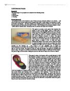
GCSE Electronic Products Research The next stage of my project is to research the following areas: ? Market ? Electronics ? Housing Market Research I am going to look at the Market to see if there are any products similar to my device. I will look to see if the product exists and is cheaper than what I could make it for because of mass production techniques. I will also analyse any existing products similar to mine and look at the good parts and bad parts and learn off them. After looking at the products similar to mine I will be able to decide what I should put into my device and what not to include. This game is purely a luck game that requires the player to pull a small trigger, when a metal ball is placed on top of the trigger it will be shot up to the top of the nails. From there it will bounce randomly off the nails and drop down to a column, different columns are worth different amounts of points. The game requires no batteries as it is not an electronic game. The size is 6.5 inches wide and 13 inches long. The game allows a player to fire 10 balls and when finished the player must count up the points and then to restart the game must remove a wooden bar which releases the balls from the columns. The game isn't popular on the internet as I only found it on two websites one of which is www.edirectory.co.uk which has the game down for a price of £23.10
3. electronics
GCSE Electronic Products Electronics Research Having researched the market for my device I will now look at the electronics for my device. All electronic devices can be broken into a simple system as you can see bellow. An example to show how electronic devices can be broken down into these three simple categories is a project I did in year 7. The project was a fan that used a thermistor to control if the fan is on or off . To the left is a picture of the fan as a finished product however, it is missing its motor and propeller in the picture. The diagram bellow is using the fan project as an example of how electronic devices can be broken down into a simple diagram. The diagram shows that the input to the fan is temperature, measured by a thermistor, which in series with variable type of resistor makes a potential divider. The control is a type of switching amplifier which in this case is a transistor; I used two in the fan set out as a Darlington pair. The output is the movement of the propeller which is moved by a motor. My system This diagram shows my system, broken down into input, control, output. The input is when a ball passes through a column which switches a switch. The control is amplification which is monostable, astable and a counter and finally the output is the visual LED display which shows the points scored. GCSE Electronic Products

Calibrating a Potentiometer sensor.
Sensor Coursework - Calibrating a Potentiometer sensor. Introduction Sensor: A device capable of detecting and responding to physical stimuli such as movement, light or heat. All sensors have an input, which can be any physical variable, Common examples include, temperature, position, light intensity, and sound. This input is then converted into a readable output, normally an electrical signal. Sensors are extensively used in the modern world, and are important components in many household electrical appliances such as ovens, computers, and televisions. The purpose of this experiment is to calibrate a sensor, which involves establishing and marking units on a measuring device. In electronic sensors, the calibration is achieved by the production of a graph with input plotted against output. From the resultant curve, expected output can by interpolated for a given input, and vice versa. Aim The aim of this investigation was to calibrate, and investigate the properties, of a sensor that finds the weight of objects. Preliminary Work What sensor should I use? The sensor to be used should have input, varied by applying different weights, to give a reasonable range of outputs. I've decided to look a few possible sensors. Sensor What it measures (input) Why used / not used Pressure The force of objects pushing down on the sensor. I'm not going to use this sensor as