
The paper discusses the issues associated with the risks assessed between the organizations bidding for ownership of Lester Electronics. As described in the scenario
Running head: PROBLEM SOLUTION: LESTER ELECTRONICS Problem Solution: Lester Electronics Nicole Hamblin University of Phoenix Problem Solution: Lester Electronics This paper shows problem solution for the organizations listed within the Lester Electronics scenario. It discusses the planning process used in determining the best avenue to take in deciding to sell or not sell the organization or to merge with another organization. It also discusses the decisions of a potential merger or buy-out of Lester Electronics, Shang-wa Electronics, Transnational Electronics Corporation, and Avral Electronics, S.A. The paper discusses the issues associated with the risks assessed between the organizations bidding for ownership of Lester Electronics. As described in the scenario, Lester Electronics is an organization that entered into an exclusive contract in the United States with Shang-wa Electronics, a small Korean manufacturer of capacitors. Lester Electronics grew rapidly making inroads with two large domestic manufacturers that use capacitors in both consumer and industrial products. Since Lester Electronics is the master distributor of electronic parts it markets its products to small and medium sized original equipment manufacturers also known as OEMs, repair facilities, and small local distributors throughout the Americas and in Europe. Lester Electronics, because of

Create a circuit that includes a sensor, which in turn will enable me to measure the volume of liquid in a container by reading the voltage from a voltmeter.
Planning Aim: The aim of this investigation is to create a circuit that includes a sensor, which in turn will enable me to measure the volume of liquid in a container by reading the voltage from a voltmeter. Plan: 1. I could use many methods to pick up a change in water level in a container. I could use a rotary potentiometer and attach it to a metal rod, then fix a cork to the metal rod, which will be used as the float that will rise with water level. I will need to use a potential divider in the circuit in order to pick up the changes in resistance, which will cause the voltage to rise or fall. 2. I could also use a length of wire, which, as it becomes immersed in water causes changes in its conductance and therefore changes in its resistance and the voltage across the circuit. I am going to use a rotary potentiometer for my investigation. [No.1] Apparatus: 6v dry cell battery pack Voltmeter Rotary Potentiometer Wires Container for water Cork Copper Rod Fixed Resistor Retort Stand Clamp & Boss Preliminary Tests: I carried out some preliminary tests with my apparatus in order to try and find the best setup for my main experiment. I tested how much water to use - because if I used under 600ml the cork wouldn't float. I examined whether to position the potentiometer so that the resistance rose when the water level rose or decreased when the water level

Electronics coursework.
Electronics coursework Remi Adeyemo 11E Situation My parents have been complaining recently of the temperature `which the car reaches when they park it anywhere due to the constant heating up of the sun. They find that it may get too hot for the dog when they leave it for short times to go shopping and they obviously cant roll down a window due to the dog escaping or theft of the vehicle. So to help solve this problem I have decided to create a heat sensitive circuit that will open the sunroof as hot air raises allowing it to escape and reducing the risk of theft and the dog escaping. The will also only be on for a set time so that theft may be reduced even further. Design brief To design a small device to open and close the sunroof. The sunroof shall be opened depending on the temperature of the time. And also close on an automatic timer so as to reduce theft. The device will also close the sunroof if the temp drops to acceptable levels in the allotted time. If the sunroof closes and it is still very warm it shall open again in about five minuets. The device shall be small and inconspicuous; it shall also be light and resistant to the elements. Also needs a mains connection so it can also be run on a car battery. Analysis Materials- insulate the circuit where needed to protect components from damp cold and wet conditions. The size should also be small as it will
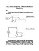
Using a Rotary Potentiometer to Detect the Position of a Robotic Arm
Using a Rotary Potentiometer to Detect the Position of a Robotic Arm Plan: A rotary variable resistor would be set up as shown mechanically and electronically: Various different fixed resistors would be tried, with several readings taken for each. I suggest 9 readings should be taken, every twenty degrees starting at 20 for each resistor. That way, a full range of angles can be tried along the whole movement of the arm. Once the results have been obtained, then graphs can be plotted to calibrate the sensor, and from these graphs the most suitable resistor can be chosen for the sensor involved. Initial experiments show that all readings will be in the range of 0 to 5 volts. Results: Voltage across sensor (V) Resistor Used in Potential Divider (ohms) Degrees 00 220 470 000 2200 4700 0000 0 0.00 0.00 0.00 0.00 0.00 0.00 0.00 20 0.35 0.17 0.08 0.04 0.02 0.01 0.00 40 3.14 2.32 .48 0.86 0.44 0.21 0.11 60 3.98 3.45 2.68 .84 .07 0.57 0.29 80 4.23 3.82 3.17 2.36 .50 0.84 0.44 00 4.42 4.10 3.60 2.87 .96 .17 0.64 20 4.46 4.22 3.78 3.13 2.24 .39 0.79 40 4.51 4.29 3.99 3.31 2.45 .59 0.92 60 4.57 4.39 4.06 3.50 2.67 .78 .05 80 4.60 4.43 4.15 3.65 2.88 .98 .22 200 4.65 4.52 4.28 3.82 3.09 2.18 .37 220 4.68 4.56 4.32 3.90 3.20 2.30 .48 240 4.71 4.60 4.38 3.99 3.31 2.42 .57
Build a sensor that detects air flow using an incandescent lamp to detect the air flow.
Aim: The aim this project is to build a sensor that detects air flow using an incandescent lamp to detect the air flow. An LED will also be included in the circuit and as the air flow increase the brightness of this LED will also increase. A voltmeter will be connected in parallel to the Led to detect the changes in voltage as the airflow changes. Introduction: The circuit will use an incandescent lamp to detect the airflow. The glass around the bulb will have to be cracked, this will expose the filament. The glass will be cracked by wrapping it round in masking tape and cracking, therefore the glass can be removed without damaging the filament. With the filament exposed to the air, a constant current source is used to slightly heat the filament. As it is heated, the resistance increases. As the air flows over the filament it is cooled down and therefore lowering the resistance. An LED which is connected in the circuit detects these changes, as the resistance decreases the LED gets brighter. A voltmeter is connected in Parallel to measure the changes in voltage giving us estimation on the airflow. There will also be a potentiometer connected to the circuit; this will allow you to vary the sensitivity to resistance of the LED. Plan: The circuit will be supplied with 12volts. I will be using a board were you have to push the components into the holes, this will
Use a sensor to make a measurement.
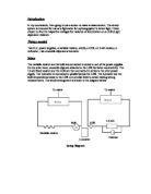
Introduction In my coursework, I am going to use a sensor to make a measurement. The sensor system is intended for use as a lightmeter for a photographer to detect light. I have chosen to find the respective voltages for variance of illumination on a LDR (Light dependent resistor). Things needed Two D.C. power supplies, a variable resistor, a bulb, a LDR, a 1.6 k? resistor, a voltmeter , two crocodile clips and a luxmeter. Setup The variable resistor and the bulb are connected in series to one of the power supplies. On the other hand, crocodile clips are attached to the LDR for better conductivity. The 1.6 k? fixed resistor and the LDR are then connected in series to the other power supply. The voltmeter is connected in parallel across the LDR. The luxmeter and the bulb are positioned close to the LDR on a similar level to avoid making wrong measurements. The whole arrangement is shown in the diagram below: Setup Diagram A Circuit diagram is also enclosed. Process Both the D.C. power supplies are switched on. The initial measurement of the power supplies is taken to ensure that readings by the voltmeter are sensible. In my experiment, this value was 5 V. The luxmeter is placed in parallel to the LDR on the same level so that the same amount of light from the bulb fall on both as much as possible. The voltmeter is also turned on and is set to read a maximum voltage
Buzzing In Electronics Investigation
Electronics Section A Buzzing In A1-Introduction I am going to design a system that will help me in a quiz game that I regularly play at my local youth club. The circuit will consist of a buzzer and two buttons, it may also have a light for each team. This will mean that when one of the buttons is pressed the circuit will latch and the light of that team will go on and the buzzer will make their teams individual tone. This will then be reset by one master switch. The buzzer must make a different tone for each team. A2-Analysis Of The Problem My system will need to sound a buzzer and light a light and also block out the other teams response to the question. It will also need to latch so that the buzzer and the light will stay on for a certain amount of time and then go off. This will let the whole of the system be able to work in a proper format with the brief and specification. I will use three subsystems in my circuit, a precedent bistable, a monostable multi-vibrator and an output voltage oscillator. The precedent bistable part of the circuit is the main part of the circuit, it will let one of the team's circuit latch so that they can light their light and sound their buzzer but will not let the other team do the same. The output voltage oscillator is the part of the circuit that makes the noise, the value of the capacitor can be changed so that the buzzer makes a
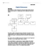
Electronics Project - Digital Metronome
Digital Metronome Planning A1: I am going to make an electronic metronome device which produces equally spaced sound at a variable speed which is displayed in beats per minute. A2: The system consists of several sub-systems. The basis of the system is the two astable oscillators. One oscillator is variable between frequencies of around 40-300 Hz by the use of a potentiometer and the other has a fixed frequency of 1Hz. The outputs of the two oscillators are put into the inputs of an AND gate and the output of the AND gate is used to drive a counter. The counter is linked to a decoder and a 7 segment display. The terminal count output of the counter is connected to the clock input of a second counter which is also linked to a decoder and a display and a third counter is also linked in this way. This sub-system thus produces a 3 digit visual output showing the frequency in Hertz of the variable astable oscillator. The output of the variable astable is also take to a series of counters and logic gates which divide the frequency of the output of the oscillator by 60 which gives an output of the same frequency in beats per minute as the frequency of the variable astable in Hertz (pulses per second). This means the display system shows the frequency of this output in beats per minute as opposed to Hertz. This output is then connected to an LED and a transistor amplifier
Building a Computer Based Measurement System
BUILDING A COMPUTER BASED LABORTARY MEASUREMENT SYSTEM Introduction: Electric systems are made up of three main parts: input, processor and output. The input is the part that would convert the input signal to a voltage, so therefore changes the form which information is presented in. the electrical signal is then passed into the processing block, which process the input information, however the signal coming out of the processing block is still an electrical signal but it has been changed, which point to it being processed. The last part of an electric system the output responds to the processed electrical signal and changes it in the form of light, heat, sound. In electric systems the input and output use devices which convert signals from one form to another. Theses are called transducers. Transducers can be divided into input transducers and output transducers. Input transducers are devices convert physical quantity such as light and temperature levels into a voltage or some other electrical quantity. A light independent resistor is responds to changes in light intensity by changing its resistance. The change in a resistance can be used in a simple circuit to produce a changing voltage. Output transducers change electronic signal back to some form of physical quantity e.g. loud speakers converts an electronic system into changes in air pressure producing sound. Electronic

To make a circuit device that can ensure that an accident and emergency bay is always lit.
To make a circuit device that can ensure that an accident and emergency bay is always lit. For this device that I am about to make I will need the following components: A power supply A light sensor An inverter A transducer driver A bulb This is what each of the components does . Power supply is the most important in this circuit because without the powered the circuit won't work. 2. Light sensor is the sensor that can detect light. 3. An inverter is the unit that does the opposite job of he whole circuit itself. For example if there is no one using the emergency room it will automatically send an electrical signal to switch of. But if someone enters the room it will also automatically switch on. 4. A transducer driver gives extra power so that the bulb can light very well. 5. Bulb works like so... an electrical current flows through the wire in the bulb so fast that it produces heat and light energy. Block diagram: Power supply Light sensor Unit Transducer driver Inverter Bulb This is how the whole circuit device works The power supply, which is the main sour of power, is connected to the light sensor, that is the sensor that senses the light around the area. This light sensor is connected to the inverter, which will send signals of what the sensor has decided to do. The inverter will then